• Happy National Barbershop Quartet Day! 💈4️⃣🎶

Solo on the Light Side

If I attempted that, I would probably end up having a fever dream resembling an LSD trip, where geometric designs danced in my sight line to the tune of some obscure Pink Floyd tune, like Several Species of Small Furry Animals Gathered Together in a Cave and Grooving with a Pict.

I admire your perseverance and they do look very cool. When I couldn't get the sides of my decks to line up with the gunwales, I stopped using them, so now I have deckless canoes, but the grab handles are sanded, at least, and once they get banged around a bit, they get dark spots on them, which greatly enhances the mediocrity.

I bought my wife a bunch of really original Valentine's presents, and a neighbourhood couple was visiting. We didn't know that he had not bought her anything, so my wife was showing the gal her nifty presents, and the neighbour lady's face kept getting darker. She gave her husband a very evil look and he said "hey hold on, I caught you four walleye out ice fishing for your Valentines present", at which point she growled at him "They are still in the sled, frozen and uncleaned". Later that night, my pal said to me "why do you have to wreck it for all men, dial that sh!t back". I'm not saying your canoe decks are in the Valentine's present orbit, but.....well.....you're making us all look bad, LOL!
 
Given one of the goals for this build is to maintain the same weight, while extending the original 15' design to 17'. Weight is going to be part of every idea/decision made along the way and sometimes you try stuff that is a bit out there, which also means there is a chance something is not going to work out like you plan.

Thwarts aren't a big part of the weight budget, but since every part is being considered ... I had an idea for them ... BALSA and fiberglass

So here is my chunk of balsa 2" x 3" x 36", very light, very pale and very boring from a wood visage vantage

IMG_7687.JPG

First issue is that balsa is quite soft and these are going to be bolted to the gunnels, so i will need some hardwood, at least where the thwart terminates and it gets bolted. So the balsa gets milled up to 1.5" x .75" pieces, a taper cut just over 4" long is added and cherry blocks to fit those tapers are cut (FYI that is more than a 10:1 skarf, so it is structural)

IMG_7690.JPG

Standard epoxy procedure, to glue the blocks on, coat with unthickened epoxy, followed by a thin layer of thickened epoxy

IMG_7693.JPG

after clamp up we have a really awkward looking balsa/cherry piece

IMG_7697.JPG

The extra cherry is taken off with the radial arm saw and then passed through the planer to get it perfectly flat. I think using my bandsaw would have been easier and safer for removing the chunk, but I discovered that using the blade on brass (as the package says is fine) really dulls the blade for wood, it needs to be changed and I got lazy.

IMG_7699.JPG

The radial saw was setup to rip the chunk down the middle

IMG_7704.JPG

and then make the cut, the pic shows what I was after ... the cut on the left side and each piece rotated 45 degrees on the right, giving a nice symmetrical triangle cut on the planer flattened surface (so ready to glue)

IMG_7706.JPG

There were a few cherry strips from another project laying around, so I added one to the middle, just because it was needed visually IMO

IMG_7708.JPG

Spring clamps are a nice method for epoxy clamping, they don't over pressure the joint

IMG_7710.JPG

One side gets roughly flattened, then on through the planer to finish the job

IMG_7720.JPG

Small taper added with the radial, this is both to trim a little weight and I think it looks better

IMG_7721.JPG


IMG_7722.JPG

A quick round over on the router and the blank is ready for sanding

IMG_7725.JPG

IMG_7730.JPG

and now the final step, adding the fiberglass. This 2 oz sleeve material I picked up along with shrink tube for epoxy layups .... this was quite expensive, but I wanted to make this work

IMG_7762.JPG

and after setting. 1) I ordered the wrong shrink tubing 2) the glass sleeving doesn't get fully clear .... both learning points, but frustrating

IMG_7781.JPG

IMG_7782.JPG

I am not going to use these, so I have to make another set. You have seen the general construction technique I am going to use, so I will skip through the second set in less detail. These will be a conventional set with no fiber glass and will use red cedar, ash and cherry.

This is the assembled glue up and tapers already cut. The thin white strips are ash and the taper is cut to just end at the strip and not cut it. The ash strips are basically the weight bearing rails, so leaving them intact is the priority, the inner cedar strip is thicker to allow for sufficient hardwood territory for the eventual bolting on.

IMG_7868.JPG

and a few more cherry blocks

IMG_7889.JPG

where I discovered the dull bandsaw blade

IMG_7891.JPG

and back to the radial for the trim instead

IMG_7892.JPG

cleaned up in the planer

IMG_7896.JPG

Setup and cut in two (again), you can see a small saw cut line on the right pair, that is from the band saw wandering, fortunately it will disappear with the epoxy glue up

IMG_7898.JPG

You can see how even the wedge shape is here

IMG_7899.JPG

Dry fit for glue up, adding cherry rail to centre

IMG_7901.JPG

and the epoxy glue up ...

IMG_7903.JPG

Quick sand with 80 grit on a flat sander to get a mostly flat surface

IMG_7907.JPG

then clean up with the planer and taking them to the final 5/8" thickness

IMG_7913.JPG

Rounding the edges with a 1/4" round over bit

IMG_7914.JPG

IMG_7916.JPG

adding in the edge taper detail using the radial saw

IMG_7918.JPG

and the finished product after sanding with foam block (80/120/180/220), ready for finish

IMG_7925.JPG

IMG_7927.JPG

This was an interesting experience, I had high hopes for the balsa fiberglass experiment, but visually it just didn't work with the sleeve I picked and the I doubt the shrink sleeve would have made much difference to the cloudy presentation. Weight wise the 2 thwarts produced weighed 135 and 150 grams (4.7 oz/5.3 oz), the difference likely epoxy application rate. These appear to be quite stiff and strong, but I won't be testing then to breakage to find out.

The replacement conventional pair was interesting, I like the general appearance more and the weights came in at 137.8 g and 137.8 g (4.9 oz), so pretty much identical. These are also quite strong, with just a little more spring ... quite suitable for purpose IMO. The outside rails are rounded over, but leaving the edge entirely covered in hardwood, this is for wear ... the hardwood will stand up better to hands and ropes that get slung around the hand holds from time to time.

The second set was made from saved scraps of other projects and did just as well as the made for purpose (read that expensive) versions, lesson for me is to not get too clever, there is not a lot of weight saving to be had in this area, so just do a simple plan for hardwood placements and don't over size and you will be in light weight territory.


Brian
 

Attachments

  • IMG_7697.JPG
    IMG_7697.JPG
    148.1 KB · Views: 3
Those look nice! I've done cedar/oak laminate beams before (seat rails and sliding mounts) and was (continue to be) well satisfied with their performance. Mine didn't turn out looking that good, but I didn't put in the effort, either.
 
This will be a bit of a cleanup post to finish the handles and thwarts part of the build.

This part of the build is a bit chaotic for me as I near completion, have to fight impatience (generally, impatience = lesson) and usually there is work progressing on several smaller things at the same time, so there isn't bigger things to write about ... most stuff is in pieces.

This post will cleanup the handles and thwarts to the installed stage (finishing/varnishing not done)

First up, handle material glueup ... the colour layout is the same as the thwarts, combining thin ash rails for strength and edge durability, narrow dark cedar for spacers and a cherry centre rail. This will be a straight glueup, just making a longer piece from which the hand holds will be cut. I find the spring clamps are pretty useful in applying just about the perfect amount of pressure for clampup and they are so much easier to add and remove.

IMG_7930.JPG

Cleaned up and thickness planed to .5 inches, you can see the colour scheme and with this much hardwood the handles are very strong.

IMG_7931.JPG

Next is a quick edge routing with a .25" roundover bit and you get this final profile. These handles are a little beefier than my normal ones, when the new vehicle gets here, the handles may be a tiedown point, so a little beef is in order IMO.

IMG_8337.JPG

The inside gunnel flat spot is about .5" deep. so some .5" stock was made up from that extra cherry piece (gunnel leftover), so that all the cherry matches (and fits). There is only about .25" thickness on the inside face, so small "extra" pieces are added for mounting purposes. The gunnels near the the stern/Bow are quite angled due to the canoe design, so some "adjustments" are made to keep all mounting surfaces flush.

In this pic, 2 extra pieces are being added to mount the bow hand hold, again spring clamps are my choice. If you look at the bottom of each extra piece, they have been angled slightly to present a flush mount surface for the hand hold.

IMG_7995.JPG

after clamping

IMG_8002.JPG

and then cleaned up a bit

IMG_8003.JPG

Vertical Forstner bit to create a parallel surface for screw (flush mount, hole goes straight down, not slanted)

IMG_8191.JPG

handle fitted and mounted

IMG_8200.JPG

The hand holds use a traditional "under the gunnel" attachment, but for thwarts I like "over the gunnel" as it leaves me more space to slide gear under.

The gunnel angle at the thwarts is not much, but it still needs some attention to create a flush mounting surface. The "extra piece" is mounted about 1/16" above the gunnel lip to allow filing the area flush after glue up.

IMG_7966.JPG

IMG_7981.JPG

To make the flush area for the gunnel to mount, I like to use a small shaping rasp, mark up the area and make it level

IMG_7974.JPG

IMG_7975.JPG

and try the thwart to check the fit

IMG_7977.JPG

For this project I am using 4 mm flat head bolts, the head is just under 3/8", so I first make a flush surface score with a forstner bit, so the bolt head sits flush, then proceed with boring a 4 mm hole through thwart and "extra piece"

IMG_8186.JPG

IMG_8185.JPG

Gluing these bits on is why the gunnel doesn't get finished until everything else is done ... I did it early once and fitting bits to a rounded surface is not fun. These mounting pieces will get a full cleanup and sanding when the gunnel gets finished, for now this gets the thwarts and handholds mounted.
 
Part 1 - this post exceeded the photo limit

The seat on this build was a bit of a design challenge. I find my usual seats aren't as comfy as I would like, with the relatively narrow cross members causing some discomfort after a few hours.

Last season, the seat in my current boat was removed and a bucket seat supported by birch ply rails was temporarily installed just to see how it would work. The seat was quite comfortable as expected, but I found it really locked me to the boat centre and interfered with body shifting to respond to waves and water conditions. This actually scared me a little out on the lake, things got a little bouncy as waves hit ... so no bucket for me.

However, the rails were a surprise to me, very light, compact and gave me an idea for how the new seats would be designed. Around this time a friend (yes Tim, if you ever read this, your seat idea spawned this one) asked for some construction critique on a seat he was putting together to serve both kneeling and seated paddling. His alternative view and my current design gelled into a wide railed, multi layered approach, which hopefully softens the impact of the rails after hours in the seat.

I have cherry set aside for the seat, but since there has been change in seat design, thin milled 2" ash strips are going to be used instead.

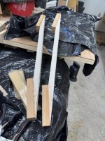
Last year I milled up a batch of ash strips for use in making a batch of paddles (planned after this build), these are just over 2" wide and ~3/32" thick. They are in the rack, it is winter ATM so I am just going to use what is on hand.

IMG_7412.JPG

IMG_7414.JPG

First step is to determine the CoB (Centre of Balance), I do this with piece of stock that fits under the inside of the gunnels and move it around until the boat balances, marking each side at that point. I double check that each mark is evenly spaced using a scrap strip and measuring along the gunnel from the end of the decks. The marks are adjusted if required and the CoB rechecked.

IMG_7936.JPG

Determining the CoB is the first step in seat construction (for me), the seat forward edge is 7" aft of the CoB .... now I can mark out where the seat is going to be placed and determine the widths for the front and rear seat rails. The rails will be bent lamination's and give gentle curves side to side and a slight dip to the front to help with leg pinch.

For the lamination's I start with some 2" x 6" material cut into appropriate lengths for the rails and cross members, for 2" strips they will need to be doubled up and planed to thickness

IMG_7938.JPG

next the curves are drawn on for each

IMG_7943.JPG

The new bandsaw does a great job of staying on the lines and giving perfect vertical, previously I used my jigsaw and sometimes got a little waver and not a vertical cut on thicker pieces .... both work and give acceptable results, but the bandsaw is so much better for this.

IMG_7944.JPG

The rails will use a 6 ply construction (~.5" thick) and I can get several pieces from each of the precut strips, 5 piles of precut strips 2 for main rails, 2 for side rails and 1 for wedges I plan on using

IMG_7946.JPG

IMG_7951.JPG

These will be epoxy lamination's, wetout with unthickened epoxy, butter with tinted thickened epoxy

IMG_7952.JPG

IMG_7956.JPG

IMG_7959.JPG

IMG_7960.JPG

Lamination's are complete, but are a bit messy

IMG_7972.JPG

To get one clean edge, I just made a small clamping jig and passed them through the saw, to get a clean edge to work from

IMG_7985.JPG

IMG_7986.JPG

The pieces got taped together, used the planer to cleanup the remaining messy edge and size the pieces to an identical width

IMG_7989.JPG

The dip on the side rails is about 1", so the front lip dips down and relieves pressure on the back of the legs, this isn't really apparent in most of the photos, so here is a shot of the piece and the mould, you can see the 1" dip pretty clear

IMG_8006.JPG

The seat is going to use simple lap joints, each backed up with the wedges I mentioned. This for looks, strength and comfort ... lap joints aren't particularly strong, so backing the joints is likely stronger, a tapered transition will lokk better and not having a hard edge on the side will likely avoid discomfort if I ever get over that far. The reason this gets mentioned here, is that since I was making the rails laminated, I also made the piece for rails laminated ... this was not a good idea, the laminated rails are quite difficult to shape and all the exposed edges look ... ummm ... ugly.

So a quick detour to make up some plain ash pieces for wedge making

IMG_8009.JPG

This offset jig made short work of making nice wedges safely ... another time that the jig takes much longer to build than the operation it does.

IMG_8020.JPG

Now the rails are measured and the wedge locations all marked on the rails ... there are wedges both top and bottom of each joint, wherever there is a 90 degree transition

IMG_8027.JPG

now each wedge is glued in place, 2 for each rail

IMG_8031.JPG

The advantage of pregluing the wedges, is they then become assembly guides for the seat. Each flat end of the wedges is cleaned up prior to final glue up. This is just prior to glue up

IMG_8044.JPG

Joints are coated in unthickened epoxy, then lightly buttered with tinted, thickened epoxy. They are put together, shock cords as clamps for and aft, then spring clamps on the lap joints

IMG_8046.JPG

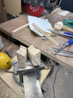
While that was setting up, I decided a few dowels might be a good addition. A Red Oak chunk from a previous project was selected as the donor, some guide holes were started with a forstner bit and the piece clamped down to drill the dowels

IMG_8051.JPG

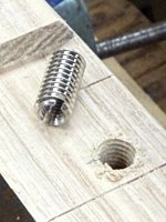
The cutter I use yields 2" x 3/8" dowels, I use a slow rpm heavy duty drill for this, battery units and most regulars drills just aren't enough torque

IMG_8054.JPG

Two ways to separate the dowels, twist with a screw driver or cut. Never had much luck with twisting, so I normally just cut at the 2" mark to release the dowels

IMG_8058.JPG

new dowels are ready

IMG_8061.JPG

Made up a marking template and marked where the dowel locations on each corner

IMG_8070.JPG

Rough shaping and joint cleanup prior to boring dowel holes

IMG_8072.JPG

Forstner bit to drill nice clean hole for the dowels in each corner

IMG_8090.JPG

Setup a work area, mixup a small batch of epoxy for the dowels, as an aside ... I stopped using pumps and switched weighing the epoxy, find a lot more reliable, these are the charts I use

IMG_8167.JPG

with the epoxy mixed up, coat the holes and dowels with unthickened epoxy and allow to stand for a few minutes (to soak in), then thicken and tint the remainder to peanut butter consistency .... coat each dowel and slide some around the inside of the holes, then insert all dowels so they protrude on the opposite side. Wipe around the base of each dowel to make a small fillet all the way around.

IMG_8094.JPG

Each dowel gets flush cut

IMG_8098.JPG

then the seat gets a general sanding to smooth out the transitions and dowels

IMG_8100.JPG

This assembles the seat, but it still needs to be installed. I started using cleats for seat installs and will use it again for this build. I made a side rail template from the gluing jib form and drew in the profile line for the cleat mounts. I am referencing off the bottom of the dark strip, the corner formed by the tap is where the seat cleat corners need to land. The blocks are positioned to show that the front edge is too high due to the side curvature, this far down, so they must be cut to yield a horizontal surface for the seat to land on.

IMG_8108.JPG

aft cleat marked for cutting

IMG_8111.JPG

after cutting the cleat is marked to make a notch for the seat to land on

IMG_8114.JPG

a series of narrow cuts made to help get a clean chisel out of the notch

IMG_8119.JPG

IMG_8120.JPG


Continued in Part 2 - next post
 

Attachments

  • IMG_8129.JPG
    IMG_8129.JPG
    118.7 KB · Views: 2
Last edited:
Part 2 -Seat construction and Install


The notch cleaned up and the bottom "extra" material marked for removal. This material doesn't really contribute much to the cleat function, so I consider it extra weight, so I take the time to remove it, additionally, I think it improves the aesthetics.

View attachment 154014

View attachment 154016

In the previous pic, you can see 2 lines drawn on the block end, these are fitting marks. When you place the block on the canoe wall, it doesn't match the curvature, just touches at the top and bottom. Two choices, rasp off that wood and get a good fit OR pack the back with epoxy and fill the void ... epoxy weighs about 4x as much as wood, you know I am fitting these pieces to keep epoxy to a minimum.


Once the cleat is fitted, a little more "extra" material is marked for removal

IMG_8140.JPG

giving us the completed cleat

IMG_8142.JPG

The location is rough sanded and guide tape placed to help manage mess when epoxy is applied. The little pencil guide mark is still just visible in the left hand corner of the notch, the block is held up by tape at this point, I am just eyeballing how it looks.

IMG_8152.JPG

Last step before mounting, drill out for the threaded insert

IMG_8156.JPG

thread the hole for the insert, using a 3 mm x 12 mm insert, the hole is 4 mm ... all standard metric threads, using these same 3 mm for fastening jobs on this build.

IMG_8157.JPG

IMG_8160.JPG

The cleat and hull are wetout, buttered and clamped ... there are two parts to the clamping solution, the wider piece in the notch, holds the cleat in position and oriented correctly, the the thinner piece is getting the clamp force from the spring clamp applied just below the gunnel. Also, I added a piece of tape over the threaded hole to keep it clean.

IMG_8165.JPG

IMG_8171.JPG

This is the seat and cleat arrangement

IMG_8177.JPG

To do the seat markup, the insert is screwed in placed with a small nail, the seat is placed and lightly tapped to mark the location. (you can still see the pencil location markers in the notch corners, it is right where it is supposed to be)

IMG_8180.JPG

The marked corner is drilled and counter bored for the marked bolt hole, then the bolt is added to hold the seat position, the next bolt is then tapped and bored, till they are all done. Is the sequential boring really needed? It just seems whenever I do them all at once, one of them fails to fit, this way they have to fit.

IMG_8181.JPG


All of the bolts are too long, which was actually planned, I can always cut them to size

IMG_8184.JPG

To install the threaded inserts, I use a thin stick to coat the inside of the threaded hole and let it stand for a few minutes, then slowly turn in the insert till it is just below grade, leave to cure and then run a 3mm tap in and out to clear out any epoxy that may have fouled threads

IMG_8208.JPG

IMG_8211.JPG

and this is where the seat is at currently, once it gets a final sanding/rounding/varnish I will add the webbing and post that as a seat install post

IMG_8377.JPG


Brian
 

Attachments

  • IMG_8160.JPG
    IMG_8160.JPG
    92.7 KB · Views: 0
Last edited:
Back
Top Bottom