• Happy Weed Appreciation Day! 🌱🌿🌻

Light Weight Solo Tripper Build

Brian
I also went through a total gear weight reduction a bit ago
Headlining that effort was my carbon copy Kite, which could have been lighter save for the carbon fiber gunwhales.
i also replaces my tent, sleeping bags (all down now) pad (Neo-Air) stove (Kelly Kettle only) and pared down on any non essentials.

i really like your no nonsense approach using your experience and desires to reach some impressive results.

BTW my low profile lately is the result of being homeless (squatting at daughter’s house while we build a new home) and other non paddling stuff like jeep rebuilds and rebuilding an insurance wrecked 40’ motorhome
I should be back in boat building mode in another year or so
 
SG,
The other half of my lightening drive (I am not getting any younger, go figure) was to pick up sewing. I made up a new bridge hammock/tarp/quilts last year that are really working for me, as with yours, all down ... even a down back cover for my camp chair.

I figured out I had made a logistical error in being so happy with the new skill, at Christmas my wife brought down her new pajamas and asked me to hem the pants ... I knew I had something wrong at that point.


Brian
 
Next on the task list are the gunnel blanks.

I picked up a 10' length of 4/4 x 7" rough cherry at my local lumber yard ($33). A quick plane to smooth the sides a bit, followed by marking and cutting it length wise to give me 2 pieces of ~ 3.5" x 7/8" x 10'.

I need about 16' for the boat, this includes some allowance, less would likely work, but when it comes to stuff like this I am not big on "likely". The 2 pieces will be skarfed together, using the 36" allowance, yielding a final length of 17' and a skarf ratio of just over 10:1.

This pic is the pieces ready to be epoxied together, they have been aligned and marked (you can see the pencil marks if you look carefully). When I do this kind of joint I like to use outside stringers and alignment blocks to keep it all straight.

DSC00367.JPG

The cut is saturated with epoxy and then I lightly butter with thickened epoxy ... in this case it is thickened with cabosil and cherry wood dust. The clamping order is:

- the left bar clamp to lock the left piece
- align the pencil marks
- right bar clamp to lock the right piece ... this effectively locks the piece horizontally, it can't slide left or right
- place the cut blocks and lightly C clamp them to align vertically
- center bar clamp, then left and right to close joint

DSC00371.JPG

Close up of alignment marks, notice how the epoxy line shows up, that is the colouring I added and should be almost gone when a finish is applied.

Finished joint, just a little light scraping is enough for now.

DSC00377.JPG

The new long length is very straight and ready to become gunnels

IMG_1508.JPG

I glued on a keeper to one end to keep the long piece of cherry from sliding during cutting

IMG_1507.JPG

Using the Skillsaw method for cutting strips, it is adjusted to ~3/8" ... gunnel blanks are born

IMG_1509.JPG

They get a quick plane down to 5/16", ripped to 5/8", then 2 for the inners are separated out and a 45 degree chamfer is added.

IMG_1583.jpg


Gunnels complete


Brian
 

Attachments

  • zVepNFjRUQJY9lonlRkCCH5GOEN5m1JZ0VDLCKAQ3Oqhpzz1EAPrc4LsuMVUyTWfKtFSPQSCQ89g_ogOgWrc4zWNiP4pLBh9kia7
    195.8 KB · Views: 19
  • 6kWNfGPTqt29t_tHCheaioge5nhrEmutm4UNpiHTQwxOrChsyAAmFaeUTCwkd6OwgW-xVUFzhW380IqU7-2bu4Uu59wwNgZna_ZB
    347.6 KB · Views: 2
  • xZJmDpupw2UMK66_rBY6xhl_JwWuobyeyanCqM9piRf5Rs5cPUcanyNCC4TBi3sD1mk32s-cY-LD0rlxmukqbGpEik5vbpu5pTEH
    252.4 KB · Views: 0
  • RM0YxRHvVKN4KWUP7GS9cjF6cVaJbfiHRONNIJW66F9VqgF9M6syJQmMWJaOQLveWsRK0AXEJuKh-BgeY0Ax0H1_sqGlxKAVsHv_
    206.6 KB · Views: 0
  • XoWDxX8JM4qlFbqpq1p7zsc3EZy3th7cUnHD7gnT-rwnf-wIVWR7xQb7142ZFlqg_iFxKxQAA_EFklbyccjsK1sgM3u0UjSIuKxr
    180.7 KB · Views: 0
  • mpym1EturBeiJPFbTAK_fQ2YEHHuD11XGjWLtNnkKJN9ptCc2GSAWPBN-SuDIphEuMW5Q9H9Dx8A-6RQD3NH72hVvbyg5J6Gg0RG
    279.4 KB · Views: 1
  • P5t19--oegR9jSdmhP8dLeonpWtWeub6Ir85nOTPw8ErU8BpUdt4VaMYR0zyOvhuXnDmTG9WH0GLG9ReRgb5mWJWQjHw1rIcakxI
    105.1 KB · Views: 2
Last edited:
For this project I need to get a starting shape and that means transferring the shape of the selected canoe (in opening post) to tables or molds or both. I am going to transfer the basic shape to a tabular form and then modify most of the shape parameters (bow/stern/width/length) to meet the criteria I have in mind for this build, then use that to create the molds for the build.

Over the past few years I have noticed a few posts asking about lofting, both "How to loft from tables to make canoe molds" and also "How to transfer a canoe shape to molds" ... I didn't find many posts covering the subject, I wrote a detailed one for transferring from tables of offsets to make the molds (link at end of post).

So this post will cover the method I used for creating a table of offsets for a given canoe shape, using the strongback and a few simple jigs. I would stress that it is not my intention to make a copy of the canoe, it is to get a starting point from which I will be changing the width/length and bow/stern profiles.

The starting canoe is 14' long and I have decided to use 15 molds, spaced at 11" apart to capture the shape. The whole operation will use the strongback as a work platform as it is designed just for these types of operation. It may create confusion, when I am trying to simplify, but when I say "mold" in this description, it is actually referring to the measuring jig that is being placed where a mold/form would sit when building a boat.

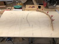
1. Mark the center of the strongback and align the middle mold support so that the mold will straddle the center line. You want the center of the mold to line up with the center line of the canoe. Obviously, this will vary somewhat with the materials being used, but I am only presenting the method, it would need to be "tweaked" to suit the shop it is being used in.
2. Draw lines every 11" from center, 7 towards the bow and 7 towards the stern ... you will have ~6" leftover from the bow/stern markers.
3. Install a mold support at each line, the support is installed on the side facing away from the end of the boat you are traveling towards. e.g. If you are doing the ones on the bow side of center, put the supports on the stern side of the lines.
4. Halfway to the stern and bow from the center, place a pair of supports for the boat, they need to be wide enough to extend beyond the gunnels at that point by a few inches and tall enough to clear the measuring jig at both the stern and bow (more on that in a few lines)

The supports are nothing fancy, here is a shot ... I believe it needed to be about 9 " high. You may need to adjust the individual heights, shimming will only take you so far.

IMG_1375.JPG

Adjust the supports so that a level placed on the center line of the boat (at the center) looks level, the ends will have a gap as the rocker will show, but the main center area should be about level .... not essential but desirable.

5. You need to make up a "measuring jig" from a rigid material, I used 12 mm baltic birch. It looks like this :

1385 mod.jpg

mine was 26" high x 24" wide, the beam is 4" wide, providing lots of rigidity. The vertical and horizontal pencil marks (every inch) were drawn in before the cut out was made, insuring all the lines were related. A note here, the bottom and outside vertical are factory lines, the top is parallel cut to the bottom line to preserve the factory alignment .... this is a pretty important point.

The jig did not need to be 24" wide, I wanted the base to extend and cover the entire strongback top to provide the best support and alignment. To help align the jig with the boat, I also placed stop blocks on the strongback which the jig fits into and a stop block on the measuring jig, so that it slides in and stops at the same place at each mold station.

IMG_1374.JPG

IMG_1376.JPG

6. Lock the canoe in place, so that it is centered on the strongback, side to side and fore and aft. Make up 2 centering blocks as shown in the pic (bow and stern), have then marked with a center line, install on the 14' mark length wise and on the strongback center line side to side (center of block to center line on stronback). Once installed at both ends the canoe is locked in place and the top center line can be determined. Just a note, those little keeper blocks do not let the canoe move side to side, they are snug.

1373 Mod.jpg

7. Attach a stiff vertical batten to both of the centering blocks, run a string between that lines up with the strongback center line (or if the canoe has a center line marked i.e. mold line or some sort of joint that may be easier to use). Put a piece of masking tape down the center of the canoe. Now measure between the battens, and make a mark at the center of the canoe on the masking tape. Make side to side (large hash) marks every 11" along the masking tape, then go back and looking down make a mark (bow to stern) at each mark, effectively making a cross hair at each mark. These marks should be aligned with the strongback and mold layout. So we have a way to align the bottom of the measuring jig and the top to a common alignment.

Will look like this

IMG_1378.JPG

8. After all of that (it is wordy, but overall not very complicated) we are ready to take some measurements. Slide the measuring jig into place and make sure it is flat against the strongback top. Push it in to the stop and lightly clamp, adjust as necessary to align the top marks side to side.

IMG_1380.JPG

For those of you noticing that piece of jatoba sitting there with anti skid cloth under it, and wondering why it was there ... it was used to push the measuring jig forward and aft as required to get the alignment right. Once you have the jig lined up both ways, we measure. Recycling a pic, this is what it looks like when you are ready to measure

IMG_1384.JPG

9. We are going to collect 2 sets of data, the "Waterline" and "Butt" data refer to what the values describe. Butt data is measured from the "Baseline" down (down being towards the canoe bottom) ... which is confusing as we always see the canoe upside down on the strongback and will think of the number as up, these are the values from the horizontal arm. Waterline is measured from center of the boat out, values from the vertical arm.

Basic measuring process Butt:
Align a ruler with the line and let it rest on the canoe surface, measure the exact distance to the top of the jig and record this value. Subtracting this value from the jig height of 26" gives you the boat point above the strongback. It's a little hard to see in the pic, but the line that aligns at the center is labelled as 0 and each corresponding line is 1 ", so I took measurements every inch. Record the position and measurement at each line, i.e. 0, 5 1/2", this would translate into 20 1/2" at 0 (26 - 5 1/2) ... so if this was station 7, you would record in the butt table 0, 20.5
Repeat at each inch marker until you are about halfway around the turn of the bilge, record all values under the Butt list for that station

IMG_1384.JPG

Basic measuring process Waterline:
This is a little different as we will also getting the sheer values
1. Measure up from the bottom of the jig to the top of the gunnel, that is the sheer height for the mold, record as ...... station , sheer
2. Measure from the side of the canoe to the edge of the measuring jig. As with the Butt measurements, subtract the measured value from the distance of the center line to the jig side edge.
3. Vertical measurements start at the inch marker above the already recorded sheer lines, continue until you reach the turning point at the bilge

I overlapped the 2 sets of measure by about 2 points, so that it showed they aligned the same (overlapped points have a line with them to denote which are which on the overlap). I entered these values into a spreadsheet to convert them to co ordinates I could use, but it could be easily done on paper as well. The Butt values for this technique are describing the hull bottom and the Waterline values are describing the vertical hull shape including the sheer

To check your measurements or to plot your values, I plot them out on paper (use whatever tools you have) like this (also covered in the lofting at the end of post):

IMG_1382.JPG


To do the bow/stern profiles, just re orientate the measuring jig against the last mold like this:

1385 mod.jpg

Perform similar measurements like this:

IMG_1384.JPG

Looking at the measuring pic, it is for the bow profile ... you can see the skid plate, don't forget to subtract it's thickness from the profile. A good guess ( mine was ~3/32") should be sufficient, as it is subtracted from each measurement. Also on the bow/stern profiles, if you intend on using stems, they need to be adjusted to allow for the stems.

This method seems to be good for about 1/32" and I believe it is plenty for purpose. i wasn't trying to do a tutorial, just a rough out of the method I used, I did delve a little deeper than this, but anyone trying this will need to adapt to the tools, skill set and shop available, so it didn't make sense to put in too much detail, you can always ask for clarification or more details.

Once I had all my data entered and developed my spread sheet to work with the data, I spent quite a bit of time "playing" with the shape, redesigning the bow/stern, finding suspicious values and going back to recheck measurements. Overall I likely spent 20 hours getting things to the way I wanted, but they did seem to work out well.

If you haven't lofted from tables, I did do a post on that as well here: http://buildersforum.bearmountainboa...php?f=9&t=4658

Brian
 
Last edited:
This is an interesting thread as I am currently involved with building a 13' solo stripper. It is the second of the same design for me. The only objective was to fill winter days with a project and use up some leftover cedar, but somewhere along the way, I decided I should attempt keeping its weight to a minimum.

I considered reducing strip thickness, but knowing I would be switching to 4oz. glass instead of 6, I opted for the standard ¼". I would however, pay little concern to the accruing pile of shavings and dust from the fairing process. I would plane and sand until fair, then go ahead, and fair some more. My tools of choice on the exterior of the hull are a small block plane and a 17in. sanding board with 80-grit paper. On the interior, I do most of the wood removal with a card scraper before switching to sandpaper wrapped about a pool-noodle.

I have always built with internal stems and wasn't going to change. I agree with an earlier comment that if a fairing fillet is needed on a stemless build the weight savings might be minimal.

I do believe stock selection can be the biggest weight reducing decision on a wood canoe. Western Red Cedar is supposed to average 23 pounds per cubic ft. or .21ounces per cubic inch. I had one board that measured .26. It broke my hart, as it was a beautiful straight-grained length of Cedar, but too danged heavy for a canoe. Stock density selection is a luxury but one that can make a big difference. I have measured densities of cedar and basswood at less than .2 oz. per cu. in… those boards have a special place on my wood rack.

My current build is off the forms and waiting for the interior glassing. After that, I will have a better idea if I can make my goal of sub 30 lbs. The first one weighs 38.5. My gunwales will be scaled down and cemented instead of screwed. No deckplates or handles, I'll put a grab loop through the stems. No hanger bolts, seat will ride on a cleat cemented to the hull. I've already built an uber-light seat that is 6 oz. less than my normal lightweight seat. If that doesn't sound like much, put 32 quarters in your hand.

Having fun building a canoe I really don't need. I think maybe I'll go fair the interior some more.
 
Another great build thread! Thank you for taking the time to document your build so thoroughly and well. I know that adds a lot of time to the build. You scored some really nice NWC to work with! I'm planning to start my first stripper next month and am following along with great interest!
 
Brian, you have devised a good method of taking the lines off another hull ! Another good use for a strongback !

Looking at form I B, it appears you have a hull depth of around 12", with a max hull width of about 27".

With the tumblehomed shear at 23".

Do you plan to single blade paddle, or use a double blade ?

Jim
 
Last edited:
Hi Jim,

If anyone would be able to pick out that much info from a pic , it would be you, not much gets past you.

I was an early adopter of double blades with my solos ... I have two, a 250 I bought and 260 I made ... both are low angle canoe paddles made for that purpose. I caught a little flack from some of the group members for not using a single, but now they seem to be the "rage'.

I have 3 planned after this build, 2 for friends with solos, another one for me.

Brian
 
Hi Conk,

When you build it is nothing but decisions, I had the same decision to make about thinner strips, lighter glass, both, none and have opted for thinner strips and 6 oz cloth. It seems we have made pretty similar decisions, hope you meet your goals.


Rick, thank you


Brian
 
At this point I have taken the base shape of the donor canoe, converted that to a standard set of offset tables. These tables where input to a Excel workbook for "massaging".

I spent 6 hours getting the shape of the donor canoe into a set of tables and checked that they all made sense. A further 20 hours was spent making modification and designing the new bow/stern sections and the 3 forms at each end that also needed modifications to support the new shapes. Sounds like a lot of time, but it includes some mockups to make sure I had figured out everything correctly. As it turns out I didn't, so it was a productive exercise.

The above step also included the prep of all the form drawings. The body forms will be transferred to 12 mm (1/2") baltic birch, while the bow/stern will be done on 18 mm ( 3/4") ply.

So, on to the next step which is actually making up the forms. Once the area on the ply is picked, a vertical line is drawn to give a vertical reference point for the drawing, the horizontal reference point is a factory edge on the ply.

In this pic, the drawing is positioned on the 12 mm ply, with small cut outs on the vertical and horizontal lines to align the drawing vertically and horizontally. It is taped in that position and a 1.5" plain finishing nail is tapped in at each measuring point/dot. Just a note here, on this form, you can see quite a few unused dots ... those are the original shape, the used ones are the revised shape.

IMG_1408.JPG

Gently lifting the drawing, you may need to place the ruler at each point and flex a bit to pop it lose. You will be left with this. the shape transfered to the wood ... you could also use carbon paper. I have done both, but prefer this as I seem to have more control. Take a thin batten and clip to each nail, draw between the nails to get the shape. Move the batten as required to complete the form shape. I include a fixed line (this one is 13 inches), this is to give a standard reference point on each form (more on that later).

IMG_1411.JPG

Once you have the form drawing completed, cut it out, staying outside the line (say ~1/8"), this will keep any splintering of the edge from destroying the drawn line and prevent those "oh dam" moments when the blade somehow wanders.

IMG_1406.JPG

To do the final "sanding to the line" I use this Rigid oscilating belt/spindle sander ... I put a 60 grit belt on and sand to the line, resulting in a near perfect shape ( I say near because ..is anything really ever perfect? ... but these are really, really good IMO)

IMG_1413.JPG

And at the end of this you have a stack like this.

IMG_1511.JPG

Took me 8 hours to do all the molds to final stage ... the wood was a bit pricey at $100, a large part of that was the baltic birch. You could substitute cheaper products, but I find this stiffer, flatter and more splinter resistant, so I am willing to pay for that.

All that debris under the strongback is the end result of about 6 months worth of projects and has to be sorted for what is usable and what gets bundled for the neighbours fire pit ... but that is for the next day.

Brian
 

Attachments

  • IMG_1411.JPG
    IMG_1411.JPG
    106.5 KB · Views: 3
Last edited:
I like the way you transfer cut lines from the paper plan to the plywood. Simple, solid and precise!
 
With the narrow shear, it said Double blade design. It's getting better every day !

A+ Brian !

When I took lines off a hull, years back, I used French curves and my eye ball, instead of the pins and Batton. It worked fine.

Your method is more correct !

Jim
 
Doing the stems up in this post, the wood will be NWC for the inner and cherry for the outter stem. No Jim I won't be going stemless this time, maybe next one, but I have enough new stuff in this build to create challenges as it is.

With the modified stern/bow shape, the strips will be going through ~180 degrees instead of the usual ~90, so I reduced the strip thickness from 1/4" to 3/16", changing the number of strips required from 3 to 4 for the 3/4" x 3/4" stems.

People successfully use a variety of glues to do the stem glue ups, but when I look at the steaming and bending process all I see is potential for voids and every glue product i have looked at, sucks at filling voids, so i just stick with epoxy. That doesn't mean glues won't hold a layup together and work quite well, it means I am a bit fussy and feel epoxy is the best choice for this job ... as with so many build decisions, you get to choose the way you build.

Sooo ... lets get on with making some curvy wood. The steam box is just 4 fence boards leftover from the fence I put in 7-8 years ago, it was cobbled together about 6 years ago for my first build. This pic is that build, it doesn't have to be fancy, that steam generator is just a pot with a hole in the lid, with some rocks to keep the lid on tight and some tygon tubing to transport steam ... it worked.

DSC03821.JPG

That pot got replaced a few years ago with an Earlex and it has been worth the investment, this is my current setup (and the cobbled box just keeps on going) ... oh, the kitty little tray is to collect any condensate that runs out, keeps it from making a mess.

IMG_1515.JPG

A pic of the strips ready to go into the steamer, I just drill a hole through the ends and push a piece of coat hanger through (using bare piece is better than using one of the plastic coated pieces)

IMG_1516.JPG

While the steamer gets up to temp, I load one of the stem molds into the vise and add a few guides around the rim, having something to butt against, makes it easier to true up the strips as they bend, next pic will explain the few extra bits at the right side of the mold.

IMG_1513.JPG

The extra bits are to capture and hold the strips with no tie downs required. The strip stack slips in and when rocked forward onto the form, get locked in place ... this means that it is one motion from the steamer, onto the form and you just rock them forward to start the bending process, no need to fiddle with a clamp or other hold down. As soon as the strips are removed from the steamer, they start to cool, this saves time right at the start where the strips are most flexible. I like to think this gives a better chance at not splitting the outer pieces. Just for the sharp eyed folk, the pic of strips ready for the steamer includes 1 extra strip .... a sacrificial strip is added to the outside to provide support and help the ones inside to bend smoother.

IMG_1520.JPG

The strips only require about 15 minutes, once the steam get rolling well, they bend very well and this is them on the mold for a few days to dry. I also draw a few alignment lines on the stack, so i can get it re aligned when I take them apart later.

IMG_1524.JPG

Once dry, I separate the stack ...inspect and clean as required, then add the tape to separate the layers and do the epoxy layup. Thinned epoxy, followed by thickened. Then assembled, aligned and clamped. I add a couple extra clamps with blocks to keep the strip stack aligned. The end hold down is useful here as well.

IMG_1527.jpg

Pulled off the molds next day and cleaned up, ready to be installed.

IMG_1530.jpg

On to getting the forms setup.

Brian
 
Last edited:
Even though we don't agree about stems vs stemless ?

I do agree Epoxy is the best choice to assemble your stems !

I need to remember this is Your build ! ;)

Jim.
 
I was an early adopter of double blades with my solos ... I have two, a 250 I bought and 260 I made ... both are low angle canoe paddles made for that purpose. I caught a little flack from some of the group members for not using a single, but now they seem to be the "rage'.

You are a man after my own heart, ignoring the inter-net “230cm” recommendation high angle nonsense. Maybe in a narrow pack canoe, even then suffering blade drippage.

The “flack” becomes harder to hear when you are out front pounding into the wind and wave. I think the newfound “rage” is simply paddlers giving up preconceived notions and group think about doubles.

I always bring a single blade, and use a long double 90% of the time. Over 250cm gets to be a custom made double, especially with carbon shaft tubes. And so worth the upcharge for a long, lightweight, low angle touring double.

We have some custom length wood laminate doubles, once beloved. Using them now I feel like I’m wielding an oak 2x6. And some economical glass and nylon doubles that are much more agreeable. But once I picked up a custom length carbon euro there was no turning back. (260 Werner carbon Camano – love that stick)

Dedicated single bladers do much the same, never look back after settling on a Zav or other carbon manufacturer.
 
Mr. McCrea, there are lots of us who only use wood and a single blade. My canoe buddy of many years recently switched to a double, and he started bringing an umbrella. He switched to the double to keep up with me, not sure about the umbrella though.
 
Mr. McCrea, there are lots of us who only use wood and a single blade. My canoe buddy of many years recently switched to a double, and he started bringing an umbrella. He switched to the double to keep up with me, not sure about the umbrella though.

Many folks double blading a canoe keep it on the down low at first, but once they come out crap starts to get more flamboyant; umbrellas, silk smoking jackets around the campfire, even their dancer name in glitter on knife sheaths.
 
Anybody can paddle a double blade ! It's like Walking ! To paddle with a single blade, you have to learn it ! It's like Dancing !

Not an exact quote, but it came from the Rutabaga Owner, Darren Bush..

I'll stick with my single blades !

Jim
 
Anybody can paddle a double blade ! It's like Walking ! To paddle with a single blade, you have to learn it ! It's like Dancing !

Not an exact quote, but it came from the Rutabaga Owner, Darren Bush..

I'll stick with my single blades !

Jim

Not to question the validity of anybody, but there is a learning curve to double blading .. in that respect it is like walking, we all had to learn and some take longer and have more bruises to prove it. You still need to know most of the same skills you do with a single blade ... they just get applied differently.


Brian
 
Back
Top