• Happy (Ancient) May Day! 🎀💈💃🏼🧺💐🍴

Hiawatha 15- Long term build

Hi all. I’'ve been ill with a cold for almost a week now plus some business travel. It doesn’'t make for very productive progress. Here'’s where we are…...

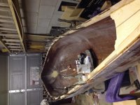
I applied the coats of epoxy to the inside and outside of the hull. I found a really nice day (17 deg.) and all went well except for the fruit flies. You'’ll get a chuckle out of this one… I had just finished the exterior of the hull. It looked fantastic. I pulled some stuff out of the garage to have enough room to move around, but didn'’t think about the fact that there were tons of fruit flies now having a hayday in my food recycle bin, because of the really warm weather. I moved it back into the garage and was bombarded by the little buggers. Guess where they went…yep, straight to the epoxy. I spent the next ½ hour tweezing them out of the finish. There were a couple I didn'’t notice until the next day. They’ll sand out though.

Anyways, on to the inwales and decks. If you remember, my outwales sit on top of the hull core with a rabbet machined into them. This means that the inwales have to sit ¼” proud of the top edge of the hull so that they will line up with the outwales once installed. I cut a small piece off the outwale stock to use as my guide when setting these up. Also, I did not want to see any fasteners holding either inwale or outwale in place , so I’m going to fasten inwale with screws first and then epoxy the outwales. I’m doing a dry run with the inwales so that I can line everything up, and don’t have the pressure of the epoxy setting up on me. I’m using steel screws to cut the threads, which will be replaced with brass screws. I predrilled 2 holes into every other scupper shoulder. I thought it would be a little over kill to do every one, especially because these will be epoxied in place. My shoulders are 3” wide, so I have about a 1” space from each end and 1” in the middle. This seems to have worked out just fine.
IMG_1317.JPG IMG_1326.JPG IMG_1325.JPG
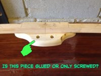
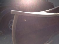
At the bow and stern, I have these nice little decks to install. They have been cut to the final shape, but not shaped. I’ll get to that in a minute.

In order for the decks to end up sitting in the correct plane to line up with the inwale and outwale, the underside of the leading edge has to be cut away. My decks are ¾” thick so I had to cut ½” away. The deck will then sit on top of the inner and outer stem bands. I like this look much better than seeing edge grain of the stems. Plus, it wouldn’t work any other way with my gunwale design.

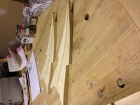
Next, the spearhead deck design calls for the inwale to be cut short of the full length of the boat and fitted into an angled shoulder. The inwales have to be installed in conjunction with the decks in order to test fit and measure for the proper length. With a little finesse, and lots of patience, I think they turned out pretty well so far. The 2 screws at the deck are long enough to go through the inwales and into the deck. They have to be installed on a slight upward angle to catch enough "meat". I hope the pictures show what I’m trying to describe for you.
IMG_1323.JPG IMG_1324.JPG IMG_1322.JPG
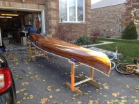
As you can see, the side view shows how steeply the bow rises compaired to the flatness of the deck. I will now have to shape this to follow the hull line, keeping in mind that I should be proud of the line by ¼”. Just like the inwales.

I hope this seems clear to you. I can take more photos, or give more detail if you want. Just let me know.

So, with inwales and decks temporarily installed, I'’ll set to work on shaping them to suit the lines of the hull. I’ll let you know how it turns out.

Thanks for joining me.
 
Last edited:
Very nice looking work. I'm excited to see those deck plates once they're finished. They look great so far.

Alan
 
As the colder weather sets in a little more each day, I’m finding it harder and harder to get out into my work space (it’s really just my garage but it sounds better when I say “workspace” ) and be productive. I do most of my fiddling around with projects in the evenings but I have no heat so it always becomes a bit more challenging when trying to do something, especially with epoxy. I do have a little space heater, but that will only do so much when I have to leave the door open for ventilation.

Last time I gave an update, I had temporarily installed the inwales and decks so that the decks could be shaped to suit the upward rise of the bow and stern. I’m happy to say that the shaping is done and I’m quite happy with the result. I have a bit finishing to do with the final shape, but that will be done with after the installation of the outwales.

I removed them, sanded and machined a ¼” radius on the bottom inside edge knowing that I wouldn’t be able to do this once they were installed on the hull. I also put a radius on the bottom edge of the decks. The top edge will have a larger radius applied after inwale install, and all sanding has been done.

I figured out that the best way for me to install the inwales and decks this final time around was to make them a sub-assembly, and then install them to the hull. The temporary screws created the thread and allowed me to replace them with brass screws. Miracle of miracles, I had no screw breakage. Woo hoo!
I know I have read this many times, but I can’t believe how much strength and rigidity the inwales alone lend to the hull. It feels nice and rigid now.

Have a look…
IMG_1334.JPG IMG_1333.JPGIMG_1332.JPG IMG_1338.JPG IMG_1337.JPG IMG_1335.JPG
You can never have too many clamps. BTW- I got these spring clamps at HD USA for $0.99 each. I can’t find them here in Canada for anything lower than $3.99. Worth it.

If you are interested in reading further, I can tell you a little about the hand plane I used to make it possible to shape the decks. If you don’t have any interest in woodworking tools, I won’t be offended if you want to leave. No worries here.

It is a radius sole hand plane Record Tools of England. Model # 020C

The picture shows the plane on the deck with the sole matched to the curve. The large screw on top of the plane changes the radius to basically whatever you want. If planning flat stock to a pre-determined curve, you would start out with a very small radius dialed in, and increase it as you remove material. It uses a standard straight blade that can be sharpened and honed just like any other. It really does work well for this kind of work, as well as curved panels, and irregular shaped items. My only complaint is that my fingers tend to hit and turn the cutting depth adjustment wheel when pushing the plane through stock. It seems that the area for your “pushing” hand needs a little re-design to bring it back and up a little. Just my opinion, but I have found the same thing no matter the type of wood, or radius to be dialed in. All in all though, a great investment. I think I have had this one, about 18 years.

Next steps… outwales. They will need to have the ends steamed to flow with the bow and stern rise. I have dry fitted them and I feel they need just a little too much pressure on them without steaming them. I have chosen not to use any fasteners on them, just epoxy. I don’t like the look of seeing fasteners. Even when plugged. Just my OCD I guess.

I’ll keep you in the loop. Bye for now
 

Attachments

  • IMG_1333.JPG
    IMG_1333.JPG
    233.8 KB · Views: 0
Momentum,
Beautiful, just beautiful. I love the look of that gracefully rising deck, it looks just right on that hull.
Your radius sole plane is cool too. I've seen them in some catalogs before. I'm curious, though. The sole plate has a window in it to allow the blade to poke through, right? Is the sole plate thickness tapered from front to middle to back? I can't imagine how the sole plate can have a uniform deflection (ie smooth radius) when the adjustment screw is actuated. The lack of a full width section where the blade passes through would cause a "kink", I should think. I've done too many years of closed form solutions to think otherwise...Anyway, clearly, it's an effective tool.

I have a plow plane from a departed uncle, stamped "Powercraft", an ancient Montgomery Wards hand tool trademark, pretty sure it is prewar (WWII) vintage. I was replicating a piece of trim for a family heirloom, and no other modern tool could duplicate the profile. Plow plane to the rescue!! I'm still impressed how effective some of these old tools can be...curved sole plane, spokeshave, plow plane, the list goes on.
 
Thanks SG. You are too kind.

I love the old tools, and even the newer ones that are based on the old tool principle. I have a little collection that is slowly building. Just like each canoe has a journey it has been on, so too with all tools.

The way the plane adjustment works is that the mechanism that holds the blade is permanently attached to the sole at the center point. When you adjust the large threaded rod, it pushes the blade mechanism downward to increase the radius. The two ends are held in place by a kind of pivot mechanism. I guess the sole is thick enough that it does not deform outside of a radius.

I hope I have explained this correctly...I may not have, so if you are still confused, let me know, and I can send in a few more shots of it.

Keep those tools telling your story.

IMG_1329.JPG
 

Attachments

  • IMG_1329.JPG
    IMG_1329.JPG
    223.8 KB · Views: 0
Last edited:
My ponderings are directed at the design of the sole plate only...
Here, I did a quick simulation and analysis to illustrate.
This first image shows the deformation of a simply supported plate with a uniform pressure distribution, a simplification. This plate is uniform is section with no cut out for a blade. See how the deformation is a nice and smooth radius?

sole%2520plate.jpg


Next is the same plate, but now with a slot in it to allow the blade to poke through. Same support, same applied pressure. See how the plate no longer deforms smoothly? It has a "kink" in it where the section is reduced. Unless the manufacturer thickened the section outboard of the slot, I can see no way to make a smooth radius. Again, clearly the tool functions well, but a close examination would likely reveal the lack of a true, uniform radius on the sole plate.

sole%2520plate%2520with%2520slot.jpg

And let me apologize for the digression, but the designer engineer in me can't look at these things without analyzing them...
 
Last edited:
I started on the gunwales the other day. Clamped them dry to the hull to see how much bending force would need to be applied to allow them to follow the bow and stern rise. There is actually quite a bit of force needed to get them to conform to the shape. While they were clamped there, over a few hours, I kept applying steaming hot towels to soften up the fibers. This worked well and the stock soon began to comply. I only have enough clamps to do one gunwale at a time, so it took 2 days to get them bent up.

Sorry, I have no pics to show. I’ll take some when I epoxy the gunwales to the hull for good.

I love the idea of being able to take this boat solo at some point, but I have a few criteria that I have determined…
*Yolk must be easily removable
*NO ugly hardware visible
*I wanted yolk to be flush with the top edge of the gunwales
*Thwarts must be installed when yolk is removed
*Center seat must be used when soloing (because my knees are shot)

So, I began working on my idea for a removable yolk. In order to have the yolk sit flush with the gunwales, I drew up a design for a piece of material that would support the yolk that I could fasten to the underside of the inwale. You can see that it’s got a little flair to it. (I’m a little obsessed with aesthetics, in case you didn’t pick that up). I don’t like to see hardware so I found these little gems. It’s a brass insert, with a ¼-20 inside thread for the corresponding threaded thumb screw. The holes in the piece I mounted to the inwales are for the thumb screws while the inserts are inserted into the bottom face of the yolk. I still have sanding to do. Have a look at the pics. I’m quite happy with the way it turned out, but am not sure how long these will last. Anyways, they can always be replaced if they don’t perform as they are not epoxied to the hull, only screwed.
IMG_1359.JPG IMG_1362.JPG IMG_1361.JPG IMG_1360.JPG IMG_1357.JPG IMG_1355.JPG
When the yolk is removed, I’ll need to have a thwart installed before and aft of the center line. I plan on making up some smaller pieces to mount them much the same way. I’ll only use 1 bolt on them though.

Thoughts from all of you who have removable yolks? Do you foresee major issues with this?
 
Looks good so far. Did you tap the threads in the yoke or just drill an undersized hole and screw in the inserts? I guess my only question would be how well do standard threads hold in hardwood? Probably not too bad considering the holding power of even small screws.

If you hung a center seat from the gunwales, perhaps utilizing the yoke hardware, would that be stiff enough to negate adding front and rear thwarts for solo use?

Alan
 
Alan, I drilled a series of progressively larger holes in some scraps until I found the one that seemed to be the right fit. I was quite careful to not strip the threads. I know how soft the brass can be.

I'd like to keep the center seat as low as possible, so I'm not sure that the yolk hardware or positioning will work for that. I'm kind of thinking of a soft leather or canvas seat that can be hung quite low from the inwales.
Not sure yet though.
Thanks for the suggestions.
 
It seems that this piece will be holding the total weight of the canoe.... meaning that ifit is only screwed on, those few small screws will be holding tthe load. Is this the case? If so, I would think that over time, the screws would work loose or even strip out. There is a quite a force there as the boat is bouncing around on your shoulders.
Jason
 

Attachments

  • fetch-picsay.jpeg
    fetch-picsay.jpeg
    94.9 KB · Views: 0
It seems that this piece will be holding the total weight of the canoe.... meaning that ifit is only screwed on, those few small screws will be holding tthe load. Is this the case? If so, I would think that over time, the screws would work loose or even strip out. There is a quite a force there as the boat is bouncing around on your shoulders.
Jason
My intention was only to screw the block in place. That way, I can replace or reconfigure as needed. I was just figuring there would be a little tweaking involved and wanted to give myself a bit of wiggle room. Glueing would only make that more difficult. I think I'll leave it as is and see what happens after the first trip in the summer.
Thanks for your suggestion
 
Well, I do need a new center thwart for the Morris to match the other two... I could send the mahogany too...
 
Well, I do need a new center thwart for the Morris to match the other two... I could send the mahogany too...
Karin, If you are serious, PM me the details of what you need and a drawing or sketch of the part and I'll have a look at it. I may even have some mahogany here.
Let me know.
Thanks
 
Despite the cooler weather creeping in, I found time last week to finish up installing the outwales. Each outwale took every single spring clamp in my arsenal. 30 to be exact. The biggest problem I had was right at the bow and stern where the point of the canoe gives no flat surface to hold the clamp. The epoxy got on the wood surface too, and made it more slippery. My solution to this was to take a spring clamp and bend the very end of the clamp surface back 90 deg. and then file some teeth into it. The teeth bite into the wood grain as long as the clamp is oriented with the grain and not across it. Problem solved. (I can send pics if any of you want to see them)

Once the first one was installed, I cut the miter on it based on the center line of the deck. This meant that I had to then cut the miter on the second piece before installing it. A little fiddling once or twice and I had it fitting pretty well. Just in case you are interested, I used a saw called a dozuki. It is a Japanese finishing saw. It cuts a very fine line on the pull stroke. Look it up.

IMG_1367.JPG

Here it is clamped…

IMG_1369.JPG

Here it is unclamped…

IMG_1372.JPG

And, now sanded, and inside and outside edge routered with ¼ radius bit. I’m not completely sold on the round over on the outwale yet. I may run a 3/8 bit over it instead. I have to sleep on it a bit. I really like the look at this point…freshly sanded, clean, untouched.

IMG_1376.JPG IMG_1375.JPG

I have a little more sanding to do on the decks, just to get rid of the small step at the inwale, but I think they look quite nice.

I have drilled a hole in preparation for a short rope in leu of a painter ring or even a small carrying thwart. I have some brass inserts that I found at LeeValley tools that were meant for holding router bits. They are made of solid brass with a 1/2" hole for the rope, and a small 1/8" flange all around. I thought this would be a nice way to finish it off. Behind where the hole is drilled, I preinstalled a 1 3/4" dia. section of dowel to relieve the pressure off the cedar with this type of thing. Sorry about the pic quality, the sun was strong.

IMG_1387.JPG

The other area I’m not 100% sold on yet, is the point where the two outwales join. I wanted to cut them back more than they are now but I’m not sure I can do that because of the rabbet that was cut into them. Have a look at the pics…you can see a gap in the underside of the outwales. I thought about filling this with epoxy and then sanding them back to whatever I want. Do you folks think this would work?

IMG_1371.JPG IMG_1378.JPG

So, with this machining, sanding, and drooling done, I have had to put the Hiawatha away for the winter. Sad really. This is the time I switch all the summer stuff from the shed to the garage so that I can put the patio furniture away, plus I have no heat to work in the garage anyways.
Here are some pics so far, and having a little fun with it.

IMG_1382.JPG IMG_1383.JPG IMG_1379.JPG IMG_1381.JPG IMG_1384.JPG IMG_1386.JPG IMG_1385.JPG

Here she is safely tucked away slung from the mezzanine floor above. Crying already

IMG_1388.JPG
Momentum
 

Attachments

  • IMG_1386.JPG
    IMG_1386.JPG
    217.3 KB · Views: 0
  • IMG_1387.JPG
    IMG_1387.JPG
    164.8 KB · Views: 0
  • IMG_1380.JPG
    IMG_1380.JPG
    178.9 KB · Views: 0
Excellent work! The gunwales looks great. It always feels good to take the boat outside for the first time, even if it's not to paddle. Sad to see it go away for the winter but if you don't have heat there's not much you can do.

As for trimming back the tips of the gunwales how about filling in that hole left from the rabbets with a small block of wood before cutting them back. Or maybe it would be easier to fit the patch after. It's an out of the way spot that won't be seen much so even filling it with thickened epoxy would probably work. Maybe instead of trying to match it go with a dark color to give a hint of contrast when viewed head on? Either way filling the hole might not be a bad idea just to keep it from holding water. I guess you've got a while to think about it. :)

Looking forward to seeing more come spring.

Alan
 
Back
Top