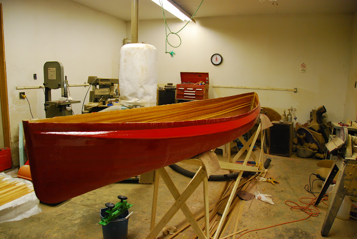
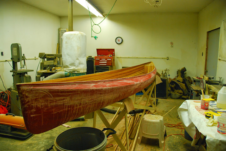
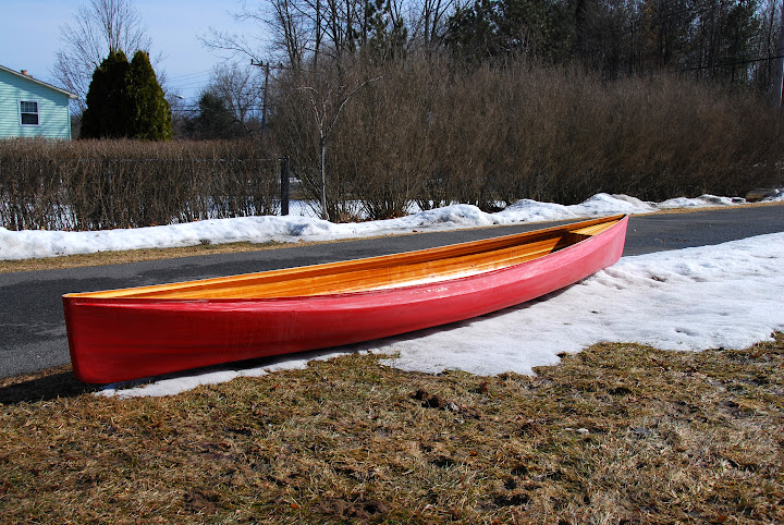
I am enjoying this chronology of a build very much. You are really doing a nice job of conveying the nuances of canoe craft. What I like best about boat building is the dream of the tripping that will take place later.
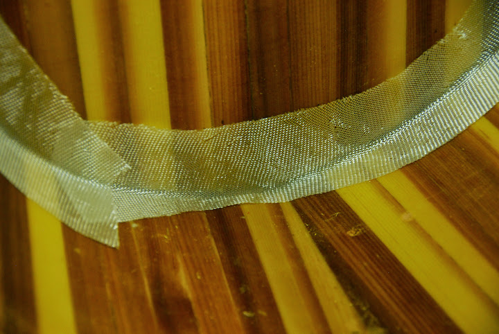
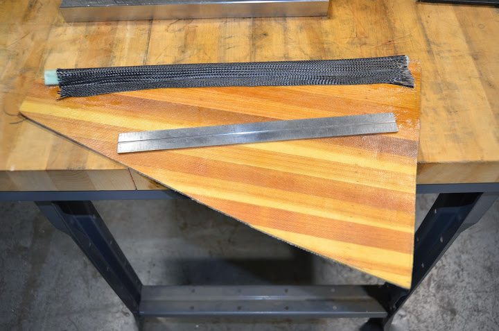
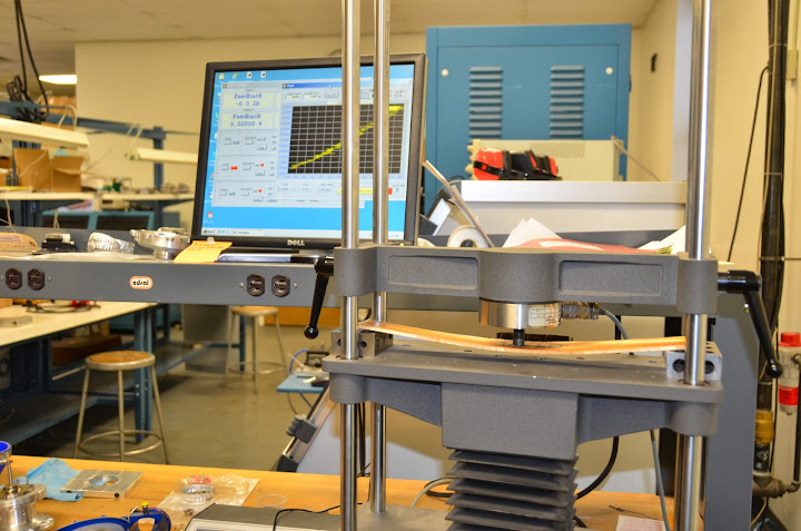
On the tip note, the final layer of the gunnel should be fibre glass tape because you do not want to sand the carbon fibre, and you will be sanding the outer layer because you are an engineer with an eye for detail. (BTW, thanks for posting the cool details of your tests.) Use "frog" tape along with poly to contain the drips and keep a heat gun handy to remove the tape as the epoxy has a habit of hanging on to the edge of the tape.
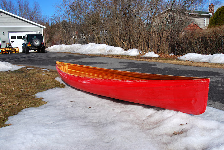
On a final note, I suppose by now you have come to the conclusion that there is no free lunch when it comes to the weight vs. strength issue concerning canoes. How much weight can you save by making thinner strips? Probably not enough to make it worth while. I could save at the most 10 lbs on my composite canoes, but I am not willing to trip with a boat that might possibly fail while I am out in the wilderness.
LF,
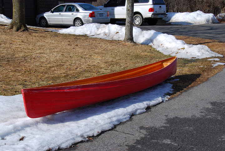
It sounds as if you build in a similar fashion to my style...performance over appearance. What good is a pretty boat that can't be used (or abused)? I built my 16'8" DY Special at 31 lbs...but that was using butt edged strips. I guess I must have sanded much more than I could measure. Near the sheer, I measured the substrate thickness and there was little loss. Around the bilge is impractical to measure, and that's likely where the disparity in material removal lies. As to weight savings, this hull has about .938 cu ft of cedar, at 22 lb/cu ft, that's over 20 lbs in cedar alone! Even a 1/32 thinner strip would yield nearly a 17% weight saving (all before sanding)...every 3 lb helps.
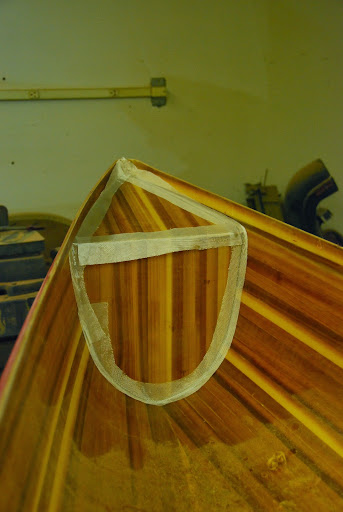
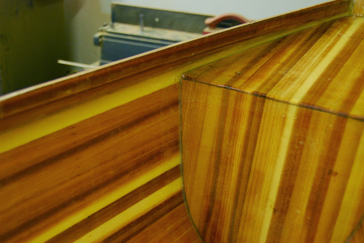
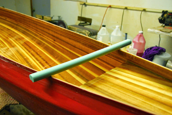
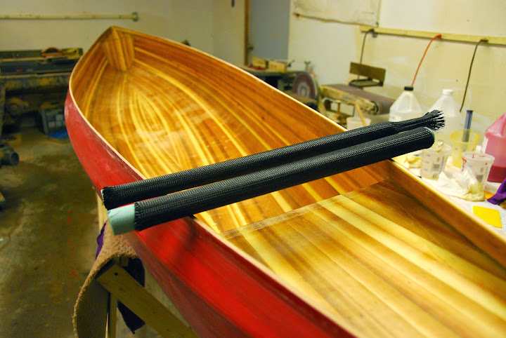
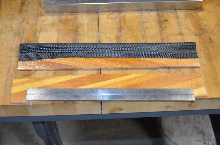
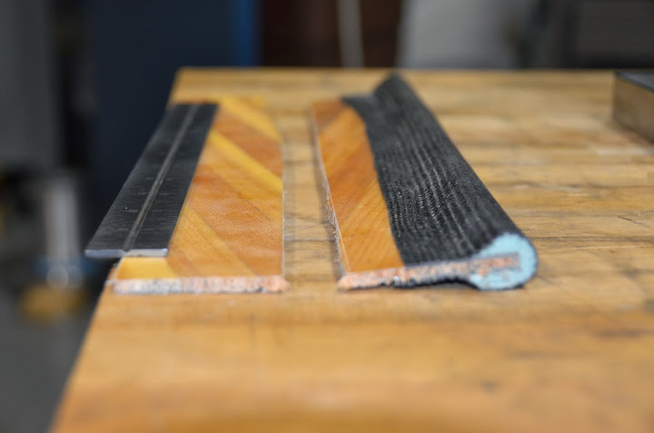
Do you have any photos to share of your gunnel construction? I'd surely like to see what you've done.
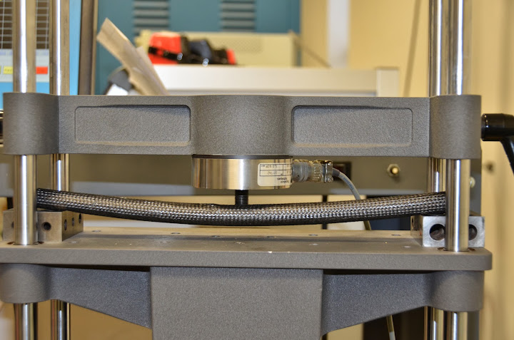
I'm surprised one layer of CF doesn't give enough stiffness (being so strong in tension). To me that seems to indicate that something is failing in the core, maybe the foam is not good enough in shear and the full loads are not being transferred to the CF. If the core isn't the problem, I'd think making the section more "T" (wider) shape would get your moment of inertia up and be a better trade.
If it is a problem with the core, I'd consider using an extra cedar strip prependicular to the shear and add a little foam under it to form it into a gunnel shape. Then CF over the whole thing. The cedar strip would be better to handle the shear stresses and the CF takes the tensile loads.
David
David,
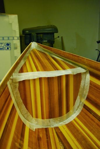
I think the single layer of CF is just too thin, I need more section to take advantage of the high tensile strength. Ultimately, the foam substrate should act only as a form, it's modulus is so far below that of the CF composite as to be insignificant... but I'm not a composites guy, my world is mostly super alloys, rotordynamics, and tribology. I do like your idea of a T section, integrating some cedar. I was thinking that the CF and foam work would be play time, I guess I have to earn my wings. I don't have a back up plan should I not be able to get the CF to work for me, so I suppose I have to do my homework.


")