• Happy National Audubon Day! 🐣🐦🦅🕊️

Building Some New Wood-Composite Paddles for 2020

Joined
Jul 18, 2016
Messages
989
Reaction score
576
Location
Bowmanville, Ontario
After every canoe build there seems to be a "need" to build a few paddles, that has held true for the last 4 canoes for me and this time is no different.

On the agenda was 3 twins and 2 singles .... 2 of the the twins are for friends and one for me, the singles are sorta for me, as I have been experimenting with a asymmetric handle design that hasn't been shared yet.


The twins are all 260 cm (8'6") long, use carbon fiber ferrules (3 positions), sport epoxy tips and fiber glassed blades. The singles also sport re enforced epoxy tips and fiberglassed blades and an oiled asymmetric grip of cherry. The shafts are either NWC or WRC with an 1/8" ash spine running the length of the paddle for strength and rigidity.


The first twin is in NWC (northern white cedar) with WRC (western red cedar) and basswood accents, 861 grams (30.75 oz)

IMG_2686.jpg

The second twin is WRC with NWC/WRC/basswood accents, weighs in at 1090 grams ( 38.9 oz)

IMG_2685.jpg

The 3rd twin ( for me) wasn't really "needed", but I was building the others and I really wanted to try this one ... the sun burst pattern. weighs in at 1070 gm (38 oz), I suspect the additional weight was the WRC I chose for colour and pattern with little regard for weight, materials make a difference.

IMG_2687.jpg

IMG_2688.jpg

The singles were a "feather" Ottertail (22.75 oz) and a striped Beavertail (23.6 oz) ... I have one of each of these already, but I have been refining an asymmetric handle and I wanted a pair with that configuration to try out. These have 34" shafts (blade shoulder to handle tip), with the handles oiled and wet sanded (with Tung oil) to 400 grit.

IMG_3052.JPG

IMG_3065.JPG

IMG_3068.JPG


Those are some shots of the finished paddles, my intent is to continue on with this post and do a detailed build thread on how I got there ... this way, you see the shiny wood first and only need to follow the build(s) if you have any interest.


Brian
 
Last edited:
My wife got me a book on paddle-making for Christmas - building a couple is on my “lockdown list” for the winter. I like the book and it will be helpful, but I’m sure I won’t learn as much from it as from your build thread Brian. Looking forward to this.
 
Once you decide to make a paddle, one of the first decisions is the "how" part of that decision. The primary paddle building techniques would be solid and composite, for the latter you get a suitable sized chunk of wood and proceed to remove all the wood that isn't paddle. While I admit, there is an attraction to that style for me, this post series is not going to be about that.

That leaves us with composite, which is making a paddle from several pieces of wood ... I guess technically, you could do a glue up similar to a solid paddle and proceed from there, but for this thread, we will stick with the idea of using the composite building technique to produce lightweight, strong and good looking paddles for everyday use.

Granted, as soon as I said "strong" and "light weight" and "good looking" in the same sentence, I realized that could mean a lot of things, depending on who was reading. First then "strong" doesn't mean attacking bear strong or leveraging stones ... just a paddle that will handle your strokes in any kind of weather and will stand up to rock and shore push offs. "Light weight" will mean sub 2 pounds for a single and not too much more for twins and "Good looking" will be left alone, as beauty (or lack there of) is in the eyes of the beholder.

While I was thinking about how to order the thread and organize pictures, I realized that with the composite build method, twin and single blade have pretty much the same structure .... blade, shaft and handle. (The assumption here, is that the twin will have some sort of ferrule to allow it to be broken down, simply because and 8'+ paddle is unwieldy, so the ferrule can be considered as an end piece/handle).

This will simplify the whole build presentation in that the posts for each step can cover both twin and single paddle versions.

First post will cover making shafts

Shafts for the paddles will all be made to the same height and width 1.5" (high) x 1.125" (wide), construction is a sandwich 1/2" of softwood (NWC/WRC) and a 1/8" ash spine. Since I am doing shafts for a "batch" of paddles, it makes sense to try and make a common size and trim it down for each paddle type, later in the process.

Material Lengths for the Twins

Twin length Final = 260 cm ( 103")
Ferrule Length = 14"
Shaft into Ferrule = 3"

The ferrule adds 8" to the paddle length (14" - 3" - 3"), therefore .... Final Length - 8" = 91" for 2 shafts or 45.5" per shaft minimum, make them ~50" to be safe. You can plan to just make a longer shaft ... say 96" and just cut it in half, this will work, but the glue up is a bit more work. The important point here is to leave yourself some margin for trimming.

Material lengths for Singles

Beavertail Blade Length = 29" , Shoulder (top of blade) to Handle Tip = 33" .... Shaft Length = 62" min.
Ottertail Blade length = 28" , Shoulder to Handle Tip = 34" .... Shaft Length = 62" min.

I like to use a Skilsaw for cutting strips, so to start with, here is a pic of the saw setup, a small piece of aluminum angle iron clamped to my skilsaw ... setup with a 1/8" gap, also note the slight bend on the part that runs on the wood, this prevents that edge digging in

IMG_2569.jpg

Strongback setup for sawing strips, setup with the ash plank ... doing the spines

IMG_2570.jpg

pic of the end supports and the plank stop, this keeps the planks from moving with the saw

IMG_2571.jpg

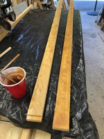
Finished as strips, sawdust all over the drive and a few extra cut, I think it may actually be a rule that you never cut exactly what you need

IMG_2573.jpg

The half inch material is cut exactly the same way, mark the plank face with a couple of horizontal pencil lines, before cutting. This allows reordering the strips back to the same plank configuration for colour matching and grain reversing for glueups

Assembling the strips and clamping with out a jig will almost certainly result in a warped shaft, so a jig to hold the shaft "flat" in 2 dimensions is pretty much essential.

This one is just a piece of birch ply with a 3/4" x 1.5" piece of strapping glued/screwed to the face. The plywood edge facing out is a factory edge, I set my saw to just take a small cut off the face of the strapping (just to the base ply) and ran it along this edge. The resulting face is parallel to the factory edge and therefore "flat. The jig gets screwed down to a flat surface (strongback or work bench). This gives a flat jig in 2 dimensions. It's a bit of work, but can used for glue ups any time you need a flat jig, so pretty often.

IMG_2755.jpg

Epoxy was used for the shaft assembly, that is a personal preference based on a) longer work time b) void filling c) can be tinted. Whenever you join light and dark woods, using a darker tinted epoxy will give a very fine dark line down the joint, this tends to create a "distinct" separation between the colours of the wood (more on that later in the thread) that helps to make them "pop".

First step is to layout the strips to be used and clamps, shims, work space ... scrambling to get stuff at the clamping stage is something I don't like, so tend to have stuff prestaged.

I like to look at the pencil marks I made when I cut the strips and flip one strip ... this helps avoid the tendency of like strips to warp when joined in the same direction.

IMG_2575.jpg

Surfaces to be joined are wetout with unthickened epoxy, I use 1" JEN brand foam brush to get the epoxy on. The epoxy batch is made big enough to do the wetout and have enough leftover to thicken for final coverage.

IMG_2584.jpg

Thicken the remaining epoxy and swap to the smaller glue bristle brush to spread the thickened epoxy on surfaces to be joined (the epoxy is darkened with wood flour, in this case cherry and cabosil/fumed silica). For those who aren't familiar with "thickened" epoxy, it is thickened using an agent such as fumed silica (mine is called cabosil) and also wood flour (aka fine sawdust), mixed to a peanut butter like consistency. This done because unthickened epoxy is quite thin and will "run" out of the joint when clamped, thickening helps keep it in place. So the initail coat of unthickened will saturate the wood surface, the thickened application will bond to this coat and remain in the joint while clamping.

IMG_2583.jpg

IMG_2581.jpg

The shaft is placed on the clamping jig, a sacrificial board added to the outer side and clamps applied, along the length, very light at this point. Add the top shim pieces, to hold the strips down with light pressure and clamp lightly till the strips are all held down. Then go back and add half turn down the length wise clamps, you will see squeeze out starting.

IMG_2579.jpg

Keeping turning the length wise clamps to apply the pressure evenly, this is not a glue joint, epoxy needs to be left in the joint ... so think turn until the clamp snugs, then add 1/4 turn, repeat down the line till they are all snug. Leave any unused epoxy in the cup sitting there to cure.

IMG_2578.jpg

At this point I usually wipe off the squeezed out epoxy as well as I can, working around the various clamps ... just because wet epoxy is a lot easier to clean off than hard epoxy. Plan the clamping for the end of the day and walk away for the night.

In the morning, check that epoxy mixing cup to see if it is hard and cured ... consider this a quality check. If the epoxy isn't hard and cured, then your shaft isn't either ... and this is why we make extra pieces. I never assume that every batch of epoxy I make is good, saving those cups has saved me a couple of times. Assuming the epoxy setup well, take off all the clamps and before releasing the new shaft, clean off any epoxy "lumps" with a carbide scraper or chisel, then hit the whole length with 60 grit loaded into a flat sanding board, sand until the epoxy side is mostly flat.

IMG_2588.jpg

IMG_2587.jpg

Use that "mostly flat" side to run along your saw guide ( I have a radial, substitute whatever you use) to remove ~1/16" from the other face and get a nice clean edge

IMG_2757.jpg

Flip over the shaft and trim the single blade shafts to 1 3/8" and the twin blade shafts to 1 1/4", leaving you with the sized shafts for each project.

A few words on the shaft sizes, the singles are 1 1/8" x 1 3/8", giving a distinct rectangle which will round out to an oval shaft, giving a nice index on the shaft handle.

The twins however will need to fit into 1 1/8" round hole so oval isn't a good idea. Well, a large oval isn't, but adding that extra 1/8" to make the shafts 1 1/4" x 1 1/8" can be handled at the 3" portion of the shaft end that fits into the ferrule, by taking off ~1/16" on each face so that it is round at that point and fits the ferrule snugly. The small lip this creates is not noticeable, but the slight oval of the shaft does create a little indexing and what I think is a better hand feel.

The ash spine allows you to go a little thinner than a softwood only shaft and still be rigid and strong ... you can vary the shaft sizing to suit your preferences. I made a softwood only shaft on my previous twin build at 1 1/4" and just trimmed down the last bit to fit the ferrule. This produced a shaft with a little bit of a "spring" as you paddled, the ash spine is a lot more rigid and weighs a bit more, so slimming the shaft to 1 1/8" x 1 1/4" compensates for the added weight.

You can vary your shaft composition using as many layers as you like, I like to mind the weight and the hardwood here provides some colour contrast and strength, i took the overall size down a bit to compensate for the added weight, but there are limits to reducing shaft size as it needs to give a good hand feel as well, I suspect even a 1/16" ash piece would have been sufficient to add the strength and stiffness I was after ...


The shafts get set aside for now and we move on to making blades.


Brian
 

Attachments

  • IMG_2581.jpg
    IMG_2581.jpg
    168.5 KB · Views: 5
Last edited:
Wow. The woodworkers on this site are amazingly skilled. Cruiser, your "sunrise" blade design is stunning and unique.
 
The blade construction will be covered in 2 posts, this is simply because I will covering how to do the patterns, as part of the post and that will lengthen it somewhat.

Up first will be the single paddle blades, an Ottertail feather and the Beavertail stripe.

For all the differences, the actual dimension of blade blanks stays pretty much the same. First step is to figure out how big the blank needs to be, looking at the Ottertail form, the max width required is ~3.25" and the length is 28", the beavertail is ~3.5' x 29" ... these blanks are going to be "butterflied" so the min thickness is 1.5", this set is 1.75"

IMG_2546.jpg

The feather paddle uses quite a few pieces of dark/medium/light wood in several thicknesses ... the individual pieces are 6" x 1.5" x (1/16,1/8,1/4) .... you can use as many or as few as you like, I find the various thicknesses add a bit to the visual. The woods are light WRC, dark WRC, Light WRC, NWC and basswood... this gives a lot of hues and variability. I line up all the strips in a long line and arrange them into a pattern I like, this one ranges from more dark at the top to more light at the bottom. This is a recycled pic from the first feather I did, to give you a visual ... the difference is this one uses more thicknesses and the colour varies top to bottom, darker at the top, moving to lighter at the bottom.

IMG_0947.JPG

Once these are arranged in the order that appeals to you (or me in this case) ... take ~1" sections/blocks and start gluing them up in sequence, I am using TB III for this

IMG_2535.jpg

Once the glue has set, use a flat sanding surface to do a rough sand on each side, don't be too fussy, just get it mostly flat, then number the block with a sequential number. Here i am using a 60 grit sheet glued on a piece of birch ply

IMG_2547.jpg

Stack of blocks growing

IMG_2548.jpg

The top blocks tend more to the dark colours

IMG_2549.jpg

Hopefully this sequence of pics will explain the process of determining the set back on each block which will allow creation of the feather pattern.

Determine the max angle that will allow obtaining the desired width, you can see the alignment, the 3.25" mark at the bottom (max width), I lock the angle in with this angle thingie

IMG_2542.jpg

The geometry is drawn in, and you see that the setback at the top is 1 3/16" and the note says to use 1 1/4", this will make the angle a bit less than max and give us some wiggle room

IMG_2543.jpg

This pic shows how that setback achieves the feather

IMG_2545.jpg

Now mark that setback on all those blocks, this pic actually shows 2 things, the setback, but also the gluing sequence. The best way I have found to do this is to just glue up the block in pairs, then 2 pairs together forming 4, etc

IMG_2550.jpg

A little further along to blocks of 4 to form a block of 8 ... doing this way really simplifies the glue up. Once you have all the blocks joined, do a few light passes through the planer. No planer, then rough sandpaper on flat surface can work fine ... don't get too fussy, it needs to be mostly flat and most of the glue removed.

IMG_2551.jpg

I don't have a joiner, or even have room for one, but fortunately there are alternatives such as a sled. Fix the wood in place, setup the saw to take off the edge and you get one flat side.

IMG_2554.jpg

IMG_2558.jpg

So that is a straight sided feather blade blank ... lets move on to get the much more straight forward strip done

This a straight forward glue up of strips, tinted epoxy is used, outside stringers to protect the blade blank, as well as shim/clamps to keep all the strips aligned vertically.

IMG_2564.jpg

Originally, there was going to be 3 single blades, notice the epoxy cups in the background above .... one of the blade glue ups had a bad epoxy setup ... so here are the 2

IMG_2565.jpg

Without the epoxy cup check, I would never had known that the epoxy, for the left one, had gone like tar and hadn't setup correctly. Enough to hold, but not set and not strong ... it's gone and we now have 2 single paddles in the thread.

Now on to completing the blade blanks. I have a radial arm saw, you will need to adapt whatever you use to get this done, most power saws will have the same capability.

Get a higher vertical guide in place and mark the center of the blank piece. I like to measure from both sides and make 2 marks, just to be sure. Align your saw blade to cut at the center point. I don't go all the way through, I use 2 passes. Flip the board end to end after the first pass, DO NOT try to just rotate the board. You can get close to the center, flipping to end will make the cut almost exactly in the same place as the first pass, rotating will almost always cause a step in the cut piece, as the blade won't likely be exactly in the center.

IMG_2758.jpg

IMG_2760.jpg

IMG_2764.jpg

IMG_2761.jpg

IMG_2762.jpg

Butterflied piece for the feather pattern

IMG_2765.jpg

and with one of the shafts we made

IMG_2766.jpg

So now we have the single blade blanks for the 2 paddles ready, next up will be getting the twin blade blanks ready


Brian
 
Last edited:
Making the twin paddle blanks is just as straight forward as the single paddle blanks, just using different patterns and keeping each post to a reasonable length.

The wavy patterns were done in a WRC base and a NWC cedar base, same pattern, different base woods and is an original pattern, the sunburst pattern is done in WRC and is my take on this pattern.

This is my blade blank for a twin paddle, it is a little different in that the top and bottom are not symmetrical, this is a low angle canoe pattern. The pattern includes marking in the shaft location and size.

ACtC-3eDcYS9UhLyYeL4FUG5vhAP7v4N6vrsVUtMHeCeYYezu_DH9XeiJg_dHM-27YmivvXqSPZI0MLmkZ3DsscbKgHF0JR4W3aDCb3fBRNgk6EUjURqkZaCofoci9BHToro9jlx2varWCFfsEqo6iPy5jZO=w1820-h1365-no?authuser=0.jpg

Play around and get a pattern you like ... I doodled until I found some curves I liked

ACtC-3f5hY-oxun1wDkSp2wS1THOoVWgvaa2JjZXkd5pU8PkVnwfZjoksgtfkv4J5PxTzwxrK4TDFSZZHsS_tWTr8pg8fUpRlKpk5XvCZcZCgb9OfYZk6NaxQ4Yd3dRyJAY-X2Vp7RTfJxfHy_PoODOknMsT=w1820-h1365-no?authuser=0.jpg

Cut a couple of patterns from doorskin ply (anything works, even cardboard) and trace the patterns, using carbon paper

ACtC-3c3TV8PU3eAB9xOHslHEnkD1v8taGkPoNT2-cDf5Bt1a5DcAvqX8gxtwdKXgl2cZBGS3w5_Xj9GnYQxFpfXOm5AbH9VwdCRDQdiDn1GPgILMhrp2GeeOvuIapk87Q9TsBhLrHVes6Hytxcw2pZ28I-J=w1820-h1365-no?authuser=0.jpg
ACtC-3ccbfnLlpI7mG7jkSt-DO-QJ8YWo4TzHT2foTTZVx-QDTYyv2jeqcQ02r5ITM3cSwRaOc5tUPh3x0RK3_YBKLDOED3TzMuwv2H982rjslQe-j2DU_DevUxfkmchT7CjbypcDGV_FTWmi9NI8mOrbCpv=w1820-h1365-no?authuser=0.jpg

and end up with the pattern set

ACtC-3f3wpXFvl7VzIoYYQhcrNttMj9308LMZYRiX79tLUaAeLWkeq2wTE0s2BOk71dwKzJQNV5d0fDU1ndcuBGazRDSy6DKm_c0zZ7qFLLmZr5sC_55ONW8n35tc9MGJIltquxNACy-dP6FNGii_LDydhr8=w1820-h1365-no?authuser=0.jpg

Glueup the rough blank material (this is 2" material, 1.75" would be a minimum), for a twin you need 4 blade blanks, so there are 2 blanks being glued up here

ACtC-3d_IiNUrKAEHz2Rlo_XvC-MAUjwxySOax4VRXYsv-dXcH7ZcS6xZrEJc1X-YXyYD7AMN7fJZa3norCNzKG_NnlF-GKVigN62eE5xWfxbAlwOFsdYhwjzsxcmY68n1_skBxrqjL5hAMvak7d2JHIfKH8=w1024-h1365-no?authuser=0.jpg

Once glued, a light plane and use the pattern to draw in the first curves

ACtC-3cqdcaWfWxZ1qES0kZmiymknoD4oKYJDAqaqIT-N6U3kcI8kYayLi-3u711Q-od0W5-pH66hAcSHZccrDKQSh5GrtbPAS7aFpVvEVIGVYuMEhALoW2uwKAZaezEcY6AJ_SGZusA6QVZZnVkeDeZc_t0=w1024-h1365-no?authuser=0.jpg

Cut that first curve, move slowly and try to get the curve as smooth as possible ...

ACtC-3ctjO83KLKVin2GmlWG1bhb5Dcfk4aWeDxmhuakGFnee-Q74J7_bPyXAHErAtNcCnwxAtYlM8w94qnYBAD1Isd6xN3N7fDKp-yqDevMM1S-z4bISSbJqiPfyga8pxiNLiMVb6wo5k3-jhfMgpJWv2Vj=w1024-h1365-no?authuser=0.jpg

smooth cut marks with sandpaper a bit and you arrive at

ACtC-3d2H2En0z2FT1cpt5bgMMmN2lWFMEXnaluHr62As2QoRopkrdyFZuEdf0ujfCLMyupbN41DIKtqmqi0-k7mCojah470u2aTzL9ipQ7_2V6VkG34ktNx-rtAC0h6yo2w3f7wA5jL8BqlDPsiyf27Dutf=w1024-h1365-no?authuser=0.jpg

The pieces used to fill in the curves are 1/16" thick, and are either NWC, WRC (dark) or basswood ... the assembly is with epoxy. The thinner pieces bend quite nicely when saturated with epoxy and require no special handling if you keep the curves moderate. As before, using a tinted epoxy to help the contrasting woods pop a bit.

The NWC with 3 pieces of dark WRC inserted

ACtC-3exQ57fFypp1pSfLYJshHWEGzyJHabcD6SJBb9PIE6lPXw0XuVpx1XFOVVuUHiSJOgLRVefNyT6R5CepY9cMVyaK1CPbVXrR_0X-tCZkT0etWINjDD8-jMkj4DafmdKqpzeLGwnikBfTbxL_o1KLJ7V=w1024-h1365-no?authuser=0.jpg

Mark up of "top" section for the second curvy piece add ... notice the face of the boards does get a little cleanup to keep it all reasonable flat

ACtC-3cV5WxiDnE7Dw3FV4Ye918XUhjjYK30L_UfwV7nNUMb0o7MWoDaW9j5F9LIrWY7IQdiq31kHgfQjvv-WjmCfQWPL6OgS4lbK1YR4a_CFn4coP1cYzZm3XaLdCVKXw_7S05jiyRxv3B_m6pglTBu1kYT=w1024-h1365-no?authuser=0.jpg

the cut and selection of insert pieces

ACtC-3cr3rjggLNyJ8XqxTaX7C5zXSoOyYWSmZyoLwB6fzlf5tTKMXBZXsTGXuFdIXweMES_Ysv297PngyoPH9dakdM2twABdWsVlu9uWinxlgeO6LJ-ikBzTOl3a0XMjb0ZL4T8Cd4x3WlRSeUYAgrMI7zD=w1024-h1365-no?authuser=0.jpg

And the 2 curve glue up, this time the WRC blank

ACtC-3eUNAEwdSN5IgBVq6PFVE7DHVT5gSv1oAefY00DaIBOMYdyBIQzsI2TxMcAHWpywQZc8NJOWeGbfvekHMwMID0SRCG_feYLwM3zdYCiEOfVVsBrw-YCUzRFjklGDXYUEHsxsujkv8UmULSmoibt8Rm0=w1024-h1365-no?authuser=0.jpg

And a summary of this technique in a single pic. Not mentioned yet on the design, normal think is that top and bottom are the same, there are no rules, so in this setup there is a single curve on the bottom and a double curve on the top, you can mix and match as suits your eye.

ACtC-3do7390ap0EqqsIZIDYqMff13aDPaAXn-PNH9sM6DDtITchFaZnpq2AERNJM5lmKyluRlrnMaoLL_pwbR0MXYHkRtyBlxdq9dRK73ZoXkcwVmpUgieGCIRaeWRv5wRaK3BSGP4jiBFokxZSng0zKWcd=w1820-h1365-no?authuser=0.jpg

Now on to the sunburst, the doodle looks like this ... the various numbers define the distance from the center point, the length of fill pieces needed and the number of each section. It is a bit of a jigsaw, but is pretty straight forward once you start.

The first inclination if you try this is to make all the cuts and try to assemble the pattern ... I don't recommend that, instead make a couple of cuts, and do the glue up, make a couple of cuts and do the glue up till you finish them all. The hardest part is getting this clamped, it is eased a lot if there are only a few joints at a time. The pic is for top and bottom, they are not the same and are handled separately. If they get made the same, it just doesn't look right ... when you do this kind of pattern you have to do some visualizing and in this case I just drew the lines to look good to my eye and then did the measurements later.

ACtC-3f-zEDNum7GOmoqArKiUJm_z5ZAKbpicugWT73LrwzTS-gFaDgawYn6lkeBnvHXY4w42FT6J9Jqp305sTFxVLlTaCqApIqu959NnAcdyddmEZLP8iDB__8qdZzVOKs0NvBNIBOSW03L-3VPmeGrq6gW=w1820-h1365-no?authuser=0.jpg

Once you get the glue up done, it is back to the sled to get a straight edge ... this pic is after initial glue up and the straight edge has been cut

ACtC-3fExVuS1GorCD9c1DIqCdNq30LVq9-TNg8j-fPTPoBrJN9RsXweUuMT-1XqicXHj86Vb1h8TINzObNZi1JYMonuwdeQ14iklY5EsLX4lUTp5VDj0LTHNAanFVsDAUQgJ8nUQ7os8EMkRNx8yFDvLaCN=w1024-h1365-no?authuser=0.jpg
There are a few steps I didn't get pics of, so a description, on how to finish the sunburst, will have to do
1) You have 1 straight side, place that on the saw guide and make the other side parallel, taking off the minimum material
2) Glue on ~3/8" piece of basswodd or NWC to the inside (where the sunburst will be
3) cut out the "sun" area, smooth and glue in a white strip and filler WRC piece.
4) Using the saw, trim off the 3/8" side to leave ~ 1/8" of the light wood
5) done

Label the top and bottom blanks (both sides) and butterfly them the same as the singles. Match using Top + Bottom for each side.

Now the twin blade blanks are complete .... next step will be installing all the blades.


Brian
 
Now that the shafts and blades have been prepared, it is time to put them together, first up, the single blades.

Attaching the blades to the middle of the shaft, maintaining alignment and getting a good clamping solution requires a little bit of planning ... this is how I tackled it.

- measure the blade thickness, measure you shaft height .... as in all things wood working you end up remeasuring often
- the difference divided by 2 gives you the spacing top and bottom to center the shaft
- pick a top and bottom of the shaft and draw in lines for the bottom 30" of the shaft

ACtC-3crAZX__4xtWVQJoZR659GEW6vzxLj5c0evRSn7kO2mxeH3zbyGq7u870T0MISQBkFq94awGskmxhvwjkkYeU86ceBEp94qW6Smu9C-A-X8p6aHuBI2PN9KFpZHQHkYFqzCQeUa2alh2mCqup39nsmI=w1820-h1365-no?authuser=0.jpg

Cut a stack of shim stock to that dimension, in this case 5/16" ... I did these up on the radial saw

ACtC-3faAZYIM_IKwwpivyU--jHsrwGJMew5uo-4XeOzpZ9ZnSaeqIOPMdvO2nq9Yta8SPQPsFlyfi0Xmy_nnRCTaapotAIdAyXH6m8VQppJQXBqJBzQqwH9qBNK1xUmahnZcPN93ZFNa3wUNWVq29ZubKQD=w1024-h1365-no?authuser=0.jpg

Shim stock is used like this

ACtC-3fsTgS_lFiE9PeVL1forKFjdjOVdlai5v4gew9GFz439dcu-OG4fgPlZxl3-Cqy4niEtQmB88yPKReMeezKalwBG2jPUqbxQT4kHMeyWuyc1l9u225J0MaTty75Qv31fYs3gwKKc63YartiCBWsz19n=w1024-h1365-no?authuser=0.jpg

Next we get the blades ready for attachment to the shafts, first step is to rough cut the shape ...so use the paddle form to draw in the blade shape

ACtC-3ebewibGNF9VxPkhk9jmNCPe169QtXvqWXm_m6r-1NEtckGBlYNvwREvrJ48iCIUD30MAFBF3nnCpwmh8XP2lqJ7y2prXoUBGhNylAjitgR_mDq2CyQGgfaYYzF10IyjR7yN4YdfopcoMJl3zjksbXW=w1024-h1365-no?authuser=0.jpg

ACtC-3cthdAO-rtRYrJzmd96MnBLDLdWmMhY6hLfMe0x9WmNqLB7iPjG0N8TgF9n8d83TVNuRlL3urSkJdxw_6fbLerxVdjp-LReUj37Ea5ls0xjEUx4nR2GNKfI1A6mONeaF3sXCTwVnrR3WaKoAVTajiTp=w1024-h1365-no?authuser=0.jpg

Rough cut the shape, staying outside the actual lines, say 1/16" to 1/8" to prevent any splintering obscuring the pencil line. There are several ways to do this, I used a jig saw as I don't have room for a band saw.

ACtC-3eSqGzsP5uoHYsViJE7kqkedZnG5vpB2O2kaPbwhd870UxuVESBwuKVgNm_U1DKizyTGPizw8UNjVTRIMNmBwWc26h8KPIT7GThh6Vo6TI9FrXQqLAnytkb_U-enVc4nSnxweUoXdK-ls_CSpNWiweU=w1024-h1365-no?authuser=0.jpg

Do not smooth the cut or discard the offcut, just put it back in place and tape ... the offcuts now create a flat clamping surface

ACtC-3fUp7Kdrhq217Ny_UashZoUIw1wCn1o-XfgZSSY04FjIaf0y3ZFFIxfkiA12OqXIIuqVlTeSrDJ_QwtyLEH-YfmqfhdNz1csSPwZHedPGFKW_y3iVrSqMFOv3vIz-TM5fcHr5nO3d2ssxdaOWHwJkIG=w1024-h1365-no?authuser=0.jpg

Clamping requires a setup that allows easy clamping around the edges, Just took a foot stool and laid a piece of scrap melamine coated MDF shelf material on top. This gives me clearance to clamp all the way around the blade shaft area. This pic also shows how to use those shims and if you look close, you can also see that it is dead center to the shaft.

Cover the central area where the epoxy may drip with some type of packing tape, 3" either side of center is good.

ACtC-3cAhwmKrPDp2rqi4Zci4T10uzwd5XN9fiY2ucvkBUGujJW95GdLHtKee5POor-22GPgHqZ0qLXhreu-NqnOvY5j1kcgvi58bfjouMnbU0QSiiU05eeFbYrwVtSey8KmDZAo8y49zMtA44Q4H-AbzZ27=w1820-h1365-no?authuser=0.jpg

Align the bottom line of the blank with the end of the shaft on one side. Move up to the top and make a mark, on the shaft, at the top, extend that mark to create lines on the sides and top of the shaft to give us something to align the blade to.

ACtC-3fmG4adgXKIOlIkXUiMslwB0SGnSs6SnO-GrQd2eu5hAsPuVwlYZqQpGpN68-F-H3lkdgJZPx3CNkVu-DxBwNPwC3K4Vq7jFjDxWkJPeVMdMOitHMBq24Du5V6yfZklnQcVBikQoNeC5SiFi4p314y9=w1820-h1365-no?authuser=0.jpg
Cleanup a space where you will be applying the epoxy and stage your clamping area with the clamps you intend to use. I use 3" C clamps to hold the blades and some 10" F clamps to lock the shaft down.

ACtC-3c1dkCD9gv3WJFMY-S5ih4t8WmtiO-_8tXV_5ukj8sdXz3aKZaleZaagP_SfylvIhRBpovv7ahMgMMYs-5_uyU6rc9_rgZDjftr-kXfwIk_FQj6yGEO8uoQBtuGDP0HFvp60ZEvcCAPLoasL7M-c9kQ=w1820-h1365-no?authuser=0.jpg

Like all wood epoxy joints, these will be saturated with unthickened epoxy, then a light coat of thickened epoxy. I mixed up a triple batch of epoxy (~66 ml) and saturated the mating surfaces of the blade and shaft.

ACtC-3d7ay8gA5Bzseq2pUkS1vm0xuNdfZTNhN4KUcuv7fJgjewPiifhGUjECVVGSkhBmyvc8hkLTzzkrspaXp37g9z6KVAqL1vhLgLTtZXbN97KuxSK6kwbRh7CUnYh1n41-BrCzheboQSJSPllUerA2j9F=w1024-h1365-no?authuser=0.jpg

ACtC-3fsgWjuHg53sB5iokxdFS-odg7bywzQwP1GLpKy_hZuMoDknd7oFUTOXdfFY4wvT-cKXx6pL6oX9qvmXkKDAL64jbsTh1zVV2PgKVqJO0pACDv5Opl1lZejmakB62g5ZtXNkjbg9Qeemdh3bxc09PJI=w1024-h1365-no?authuser=0.jpg
The remainder of the epoxy was thickened with cabosil and cherry wood flour to the consistency of peanut butter and applied to both mating surfaces

ACtC-3d9N3A4uyZI03eRSLTcVCEblN2wkwSjKWMTNOHOaV8DENg1WatVxJfw4HnQrbqUNGBsKPM_oaOLEAMjUBCf3xU8sCUYLOQJ3Q9Ru-Om-TO0CtkL63JnhsOaPcb2w6Lrn74BXSMPWrSpYpHTPYXYTQb0=w1024-h1365-no?authuser=0.jpg

Clamp the shaft in place using F clamps or whatever you decide to use, this pic is from earlier, but it does show how the clamping is done

ACtC-3crAZX__4xtWVQJoZR659GEW6vzxLj5c0evRSn7kO2mxeH3zbyGq7u870T0MISQBkFq94awGskmxhvwjkkYeU86ceBEp94qW6Smu9C-A-X8p6aHuBI2PN9KFpZHQHkYFqzCQeUa2alh2mCqup39nsmI=w1820-h1365-no?authuser=0.jpg

Lay the shims mostly vertical/out from the shaft, leaving about 1/2" between the shims and the shaft. Carefully align both blades to the top pencil mark. Then add a few clamps to lightly hold the blades to the shims ... don't worry about getting the blades close to the shaft, just near aligned and held down

ACtC-3dH3d6wRvdZo-vkcwSJyQgm3XH0VyBJqqoGhhlO2VkCeQHDQMDJGHPzKpSidYjFfW110OnhZNlLHZH14MDx_bW9CPIGh4T4sVqCxqM0f6d1bm7fkyHcCEgZWAdQgbQIbi-TYZUewkqwbz3V7LUKUvNW=w1024-h1365-no?authuser=0.jpg

Place a couple of F clamps side to side at the top and bottom positions and clamp lightly, do a final alignment of the top marks. Then do a double check that the bottom is also aligned and that the 2 blades look aligned. Add a couple more F Clamps and tighten them all down snug, remember this is epoxy, once you start seeing squeeze out you are almost done. Once the clamps feel snug go another 1/4 to 1/2 turn more and you should see squeeze out all along the joint.

ACtC-3emtvTazGwo_zWm1r-nh0m4wCb0eTP1k6_9CwrqTGBMnS3lS5a4H0civAqQ0Tyba3uOFFqk7LZdEPeBzkq3lWut3dTiSVDjnV3iWwCdMXh0C3mySiMAR0MBLDxNsuTXZPOeUzPGjGzQG9BK3-HUoNHt=w1024-h1365-no?authuser=0.jpg

ACtC-3dg9SwGCN6O9PZUbLZ6RYgVE1SyWpPkFZ-QJV76MFUrhps3FjKvHeUc0sBS1H_J-KW5puWFv-FEkSyuMKN9ueACQKh691PlrdbQzubI-SUV2_4HGOQ4x5ZVx6rT8-SDsd02pNd5yeY7Zue44rYZ7xm4=w1820-h1365-no?authuser=0.jpg

ACtC-3dW2K6kv2KVSamJiQyFxG214DwaZyM5frBPzoytYj_DyztX-uVH7B_ppyp_lUSp8KtK3lXDwaMs1GqiwNlK6IIqdq6iIvpWuRDUY69kESfieAxq4Ce8D62qYChn9C3vEv1H1u9fY0foa3HWzcTbhJnH=w1024-h1365-no?authuser=0.jpg

Next day, remove the clamps and you should have something like this

ACtC-3cP5IM4SrWAAS6tbTEyS6wkNKwX0ma_AmvA18qENXk-sX8LCbkvJOFb5Si-80a3w05xXpMdtLxLDZTgb735qE4pq-uZyH6I43CvTUtYqLMqBWhA3qO8PoB7s0UaTVShQGRTzC43yL6C2vCiYo7G0f2_=w1024-h1365-no?authuser=0.jpg

Last step is to sand down to the final shape, I use my vertical sanding belt to get it just to the line.

ACtC-3cIlTKEE_SlyWshvH-t9zeA4PUOd9i5lpsQKnDmlBSr_uACAVkidZWHA34zoXf6b-L3hJZsij72IoGgSgx9GiBfxTUkjydPBy9CboGzS7w215DOM8wppU5SfWQvCULRNLfAGoBT9XSFp2_vfLaN8y_H=w1024-h1365-no?authuser=0.jpg

And the single blades are attached and have the final blade outline complete

ACtC-3eKgwCOB8eiZJ7rdKenhY71q3mH4xu3649LB8SlxL62i7xLYUsutMuyyIk51_kC70mu8h5GRJ83hq7UsgYORQeHlr9NPWMpSML9efZ-T2tby77cK4AKfpcuAsT83bob70DLhVp8kUaJMJR1GoHDsliO=w1024-h1365-no?authuser=0.jpg

One thing to keep in mind when doing some of the smoothing and handling steps is that a lot of these operations are assembly and not the last operation. The tip area can be a little irregular at this point, but about 3/8" of that will be carved away for the epoxy tip, so it isn't a worry now, just get it rounded to right shape. The line of epoxy we left at the joint can be wiped off at the clamping phase, but the final blade thickness will have all of that area carved away as well, trying to wipe around the clamps can make a mess ... I just leave that and get it later.

Double blades will be covered next post.

Brian
 
The operations to attach and do the initial shaping of the blades is close for both types, but not identical. These twin blades are going to have a curve and that needs to be cut before the blade shape is done ... with the jig and method I use, it is easier to clamp and hold the initial square shape of the paddle blades.

The same clamping jig style is used, this pic shows bar clamps and C clamps, the significance is simply that all the clamping was done at the same time, I used the F clamps on the singles, and had to go outdoors (garage gets cramped) and use bar clamps on the twins. If you look at the pic, you see another difference, the blank is not centered on the shaft, but at one edge. Also visible is a center line drawn on the blade blanks and a matching line on the shaft, that allows you to get the blades aligned during the clamping process.

The biggest difference you really have to pay attention to is blade blank placement ... there are two halves to a twin, the blade is aligned with one edge of the shaft, this effectively creates a left and right paddle. Iy is possible to create two lefts or two rights at this point. Also, you need to keep track where each blank is placed, there is a top and bottom, you can also mismatch side to side.

The easiest way I found to deal with this, is the clamping orientation in the pic, the pieces are clamped in assembly orientation, that way it is easy to see what you have side to side and top to bottom.

ACtC-3eY_8MNyDxKT5Um9u-1CV_SJHaWg385aqmCX2QGDnyat_a0kdlVpbkB3K_bMTuBZPdsipHCpadKXwlwdlq_eN5bsr-XpzeYUU1bbZ0XWdpEoFG_PiF09UkX7sYfIVQkGFCee3Ol7JkJnl996f35ZSQD=w1820-h1365-no?authuser=0.jpg

Removed from the clamps and ready for the next step, which is adding that curve to the power face

ACtC-3fcPsjKubC8I2UHsYZTyoE1MRqr_JdKLrdMBnDVCzipp8OGiqSH0WnnS08ZaN-d_H02pHsD9ZBgMiyMIMLeTY213if0_N6pKY3nEC98PHIfEoE6-shrrUdIG1QqoTc6UbmS7ZCy91T8A1hkqtaBYzL_=w1024-h1365-no?authuser=0.jpg

I made up a guide for my router, that allows me to carve a 21" long blade and create an arc with a mac depth of ~5/8" ... these are recycled pics from the first twin I carved

The jig with the twin form to show sizing

ACtC-3eGPMrPFufgtGslr7k3GvkF0RFDzFnTHDIz9nJrklEXMRoYUKsWHQqlvxBPm_mfxl5GY-sVq0T41vkamv-_Obe1LhknW38ySmRyCGR3EgH-pSYx-6UgFNaJHDh8s-xrQrBUXQuUfh0iIcpSP-5zeNJT=w1024-h1365-no?authuser=0.jpg

The initial test board, looking at the uncarved area on the far side, gives a good idea of the curve

ACtC-3f-eSSAwynBmCS79bxojOIgEuGlluW0yhNe2FkQPBffxFJR8Ei2zMw48l5eI9q2OMkzBPmCqz7UyviIHazp2tRd2dOdNzns2yBqa2ytmi0FSJOhXVON6pOF5iSc8EdABcxP7C7-mu4J_Z7oMnnibvBR=w1820-h1365-no?authuser=0.jpg

With a paddle clamped and router board, the little wood pieces on the bottom, limit side to side travel

ACtC-3drjOjiEjSQTrPHx_l8G-P6Tmbw-Vt5lxaJoEJQgD9WA0io_J8VM6Tcf5CSKeuwAMDiV3hZBlfLVtESZkzMs2dezrbieGxMhTpWt6eSH0qwlSgoDrjq5YRoJkphrOepxBxQZnceLYTj88WHtD2NQJEL=w1024-h1365-no?authuser=0.jpg

This is the 3rd set of twins and the clamping has evolved a bit. Shims have been added to allow the shaft to be clamped easier, spring clamps are used to hold the one end firmly in place. The spring clamps are located at the very edge of the cut area and should never see the router blade as that area stays flat.

ACtC-3d6MIMNGPA6lt3seQMXJe7O2u_BNaCydPpny2FqbQvSNp6X6jyOq8whDdJj9gcwegL6Wp9-BpwlkLWVVw3Hiu8aH9ynpyUmGww9ERXNS8qEHsj15MshtN15dErDXFJZK3-ngYaP2IzQc1WqMgXp14FZ=w1024-h1365-no?authuser=0.jpg

Take small, successive cuts with the router, it is much easier to control the cut if you are taking small amounts each time. The router board has the stops to prevent going too far at the sides, the curve prevents cutting too far fore and aft. The only tricky part is leaving some of the shaft in place as you carve the face. I like to step it a bit as shown in the pic, this is to give me some material to carve a bit of a spine in the face. I believe it adds visual appeal and helps the water flow around the blade a bit better and creates less turbulence ( that is an opinion, I have no hydrodynamic proof that is the case, just what appears from use).

ACtC-3cOsRM9cEpTT-hptE7N069agFw1bj3eqhDrzqf_p_aZJulklvBBiTXgvDRS2OS8wNVaOk4p8UQfR3yhCxFC21WPnWl7e43kj7_4SxqELQ3VAuCYD7J_l1U9B3zxOL34_O5RzgoYXTI74ssuUBgstGQ7=w1820-h1365-no?authuser=0.jpg

ACtC-3e0cqKuQ9HWJO6-SDH2fsWEyCdsUhpuBFnAECE7n0wJPnEr6XI_U_QKkSpNcLZrFencS8Ked5pv0AGGLJgWmFtS8gGINjoaXMAMezXa6kbq2qZ8-s5SdMKpmN_Iz8heKInggFRLC8Ge2gGAP6misNsX=w1024-h1365-no?authuser=0.jpg

For carving the spine I use a couple of items, a Japanese rasp, an Italian rasp and my ROS .... don't get too aggressive with any of them, I like to do a taper from shaft to about the blade center, the shape is rounded at the top with convex sides that blend into the blade face.

One done, one to do

ACtC-3e4uEgaljEmzO-FfFAhF_y-J_5TnrwT8Q4H2ypWStKPyE972Kq8m9FEjn30kScoK7o_ThVJ3UxUj7AL11rBjd1Tw2R1xoEZSOChzWhmSRU7Jl1mHOUjN62LoDEJbcGkviu5HPSHhBjckvNt9RyYGAJk=w1024-h1365-no?authuser=0.jpg

Mark the center of the blade and align the twin form with that to draw in the blade shape

ACtC-3eXquUmQppI8Gof4iC69JD4C3-rd7TAKoa-oiHZtgfrALX68NlVNMEW-rRLcvtvKn_bf28v9VR4PpTTZIHa21O_Jw15hCg_dsoeYONmjA-gL4fttFsiZJb5OIPYai_lp36Og7xT2Vp4m8vB-hLUQ04H=w1024-h1365-no?authuser=0.jpg

ACtC-3cpA1NwoeEHe1EQJeLbeykKTzgkuk2wZwW7Qh2sLf3p0J0KVGLrNE7I349U6AUNShtCxvlneEas4t6qAoXX48D0gSByqBSETdj4VOvtHGNMJGriS4ivLJllfkNkFrOQ0pfG9jUIR2GyyCF1KbWO4gZ1=w1024-h1365-no?authuser=0.jpg

Just a note about the pic above, if you look at the blade with the blade form drawn in , the blade blanks for top and bottom were done slightly differently, the bottom was done with TB III, the top was done with dark tinted epoxy. Looking at the 2 blades together, the lines on the left pop more than those on the right ... even at this stage of completion the impact of the 2 gluing techniques is apparent, it gets more pronounced as finishing proceeds.

The sunburst gets set aside and the others are completed

ACtC-3flgJTABHoEJKtmjUN_tqQJ808BfUWEGqeJkIlywfrsVbLiJIbBiWAX5LZQkTGEf7TXlmVenusU-NZ9uxeUCGy77-_KiYeYTf1s-F4kiY6bf6Gn8mBHlx8IVo5-ikxqbDhhb-rp1cEx2N1YiY6XihxX=w1024-h1365-no?authuser=0.jpg

Cut out the paddle shape, staying a bit outside the line, as before. The final shaping is done on the vertical belt sander.

ACtC-3dUdyVVd0VbIFA5_88gK1I2rQe4Th3YjhCwIOVsXib2iZacoYy6UaVdzEGoZABvfNla9qYtf7MiXIa-6ad5gOWsX61uV3gV6JVSTBuOFCfTARkSthR9C6h-LAOmobfUgwhcGOsvIrLv0wCvhku-O0gL=w1024-h1365-no?authuser=0.jpg

Some of the detail gets drops when i am repeating a process already covered in a previous section, if something doesn't seem clear, just ask.


Brian
 
Those laminated blanks look great and I can only imagine much pleasure there was creating and carving them into useable paddles. Only had a quick look so far but I will reread through the entire process, lots of details mentioned that add knowledge... outstanding stuff, Brian.
 
Nice Work Brian !
No Lack of imagination in those paddles ! ! Wow !

I really like how you set up your Strongback, for strip cutting !

Oh and the Oscilating Belt sander. It is on my Next years Christmas list ! How handy would that be for fitting strips too ? !

Great Craftsmanship !

Jim
 
Missed the blade shaping jig, with the DeWalt Router. A sort of Cove cut. Do you change the guide rails, to do a Bead cut and flip the paddle ?

What router bit did you use for this ?

Again nice work !

Jim
 
Hi Jim, the router rides on the rails, the rails have the curve. You adjust the cut depth till touches the wood, do a cut, adjust, do a cut ... you watch where the cut ends and stop when you get about 3/4" from the ends. At that point the the curve covers the length of the blade and has removed about 5/8" in the center and nothing at the ends.

The bit is a flat bottomed, 1/2" plunge bit ... similar to this one https://www.busybeetools.com/products/1-2in-straight-router-bit-1-2in-shank.html

At this point it is only cut on one side of the blade ... it should be clear in the next 2 installments, there will be another one on finishing the carving on the twins ... unfortunately, I can't always completely cover a process, because the process isn't done all at once .... or it gets too long to post easily.

Brian
 
Time to get some shaping done, the single blades will be tackled first.

First off, this is the book I started with and it has a lot good information and techniques ... it will give you a good base to grow from, once you go through the process, you quickly develop new ideas and processes to get the job done for your situation. I still use a few of the templates and I have also created some of my own. There are other books available, this just happens to be the one I settled on and I liked what it provided.

ACtC-3cHnfao-PejiMcxA9THhHJftHELdyCyQPB3ukh_KEa7zzfj7vXGp0Vt2qDGrKJ9X82PbL2i7gMr_vc_RhhN6Z5UnOSwrigR-tgDJm9UyXKiGdBQnXArDjUfw4OG5W6vdP1YpNfIAhWca9S65ls81eUs=w1024-h1365-no?authuser=0.jpg

Before wood starts flying, we need to draw in a few guidelines, one for the throat area (where the blade turns into shaft) and another set for the blade thickness.

The throat area template comes straight out of the book, I like to use heavy cardboard for this one, because it needs to bend with the blade shape

ACtC-3egKr8-tEs6TxRVjxXYD5qJ79pzd4k7FaYbn5F5CsLpFeXtSiNHYnIXyliITqNFjIJ05qWLL7tYRUYuwgw8XJeQHrHeMeI5qoKk2FlSI_Lc1go821xP4MYy2gb455QMQOQRM0OnA1pGflHg6v7VefgC=w1024-h1365-no?authuser=0.jpg

Put the base of the template in place and draw in the shape centered on the shaft/blade

ACtC-3feBUbC0ISaJ0CcoMafpqf-VUs6e0uLjD9aGAGEznbwp_GvZdTnTc7RnnARhz4FaXDCrxBAIeS_khWyMjWsVB4KV8UANo6JhWG1-Fs2pAw3SR4JC6ELrZd3Jw8BCd_fAk4w2MoPAbf45zVZvZeyF-De=w1024-h1365-no?authuser=0.jpg

Next we draw in the guide lines on the paddle blade, these will have 3/16" edges, I setup my Incra marking tool ... take 1/2 blade thickness + 1/2 edge thickness (3/32" in this case) and draw lines from either side of the blade, check that the lines do indeed give the desired 3/16" gap/guideline.

ACtC-3cvJxyRdJgounIqspcbXsS-NENwg5Y9q0yEL8PTUvoArH6Y6NxcZRjYMcn1sUFo35qikDvy_3ndy-tXsiJprTESeqgQBegIqF9mh_x1rxhnIrFEsriFCVrxcv9C-EyzPyaO48FjJdPRJrdl6asNgHkj=w1820-h1365-no?authuser=0.jpg

ACtC-3dyWwzcQ-TGRR1SQxysc0stORCD4ti2UlCsK43Pvb_e9annX0a6TtZZHYp2Rgb2LMuZb91HDSQeaSERgFCxMdb0D2fdE_AXr_lDV6pf6CfqsPY7S6m9XkxkB3QFfHPGmZ2T8KruzWNtlnyxJUB_WkO5=w1024-h1365-no?authuser=0.jpg

This is how the marked up paddle will/should look before we start removing stuff.

ACtC-3f9r2pLFspH9XkrV7pJr5XdUIsCQcSbBdkfOTpiJgpAgxERbF3-hG6uTBPHQ4Q4thE59cFk32XrxZauGDO2HFLi5o-SrykBjmFeL3fVqKCN9l450_MZZbbqk7CbKG0NjBX32JGTZVmoopDqs-Kq847m=w1820-h1365-no?authuser=0.jpg

I like the look of a small spine down the shaft, first step is to start by taking most of the extra shaft material off, using a gentle slope from the shoulder (where the shaft meets the blade) extending about 6 " . You can see in the pic that we have lots of material to work with, so creating a slight spine isn't an issue at this point. I like to use a longer hand plane for this, but for a lot of this removal my rarely used power plane is really about the best tool I have found for the bulk removal.

ACtC-3eiMMPX0n4sxWvo9uk3GvmIdnBomTI2drYLzntPDiWFBnMaILRtHck4i_tnt_zsn7EzxWr7_AuHfc-g7BSWZ-jlXUklSgREloUACQ5OKw5UlQdRWBKE9NypKCZNjwuyCRvTemVcoJMUDhzELCYXMv8b=w1820-h1365-no?authuser=0.jpg

I use light passes with the power plane, using the lines for guidance ... to keep removal fairly even and flat till about this point

ACtC-3fvWMFiJwxvH_Qsx8RKGMMmzzs5X-sXDWmuhJ1V8zNnfW3U116xVF_zg1Qo18zzeB7cwj3ZFQhbvNRC4zh-BVt3K3zWgaAXE5EySiIgt3Ft0COfZokpYaP3P2wbDB1XxavCPQPI7rxrRQXzgyWOmy_1=w1820-h1365-no?authuser=0.jpg

With about 1/8" to go from a relatively flat face, start to remove a bit more at the edges, creating a shallow slope from the shaft to the blade edge, in the pic, the left edge is just about where it needs to be, the right edge hasn't been done yet. This is to give a visual to the operation, after all this is carving, you will need to gauge where you in the process, but the guidance lines and shallow passes make this fairly straight forward.

ACtC-3ev-jFIpbrEBRdYVfa6IIA1-Um761Ogwcs7DaGEOpoUygKjgqEm-XW8yrsC1Z5uNkfngwYAJeasn4DHJp_D9g-dWTJvitqGV8e6kYpYZNKCvkHnUpXvYI5Lq-KAuKA_IIoeAKzgmGDWl0KTm8gJBUcz=w1024-h1365-no?authuser=0.jpg

Once you have both sides roughly to the edge guidance lines, the paddle flips and you do the other side, looking at the bottom, you can see that has been carved close to the guidance line. One important point about the carving process, leave some room at the throat area, don't go to the lines, just near. The shaft hasn't been carved yet and this area where the throat and shaft meet, gets carved/shaped to give a graceful transition.

The reason we haven't carved the shaft yet is simple, all this carving requires some form of clamping to keep the paddle still while remove wood, a flat shaft is a lot easier to clamp, likewise we haven't put the handle in place yet, again, a simple rectangular shaft is easiest to clamp.

ACtC-3foTK1Pbdvkur25Tvd6T25hz3sKKMU5wU0Jf6J3-98efKTnMjBIuqd9O_5f_dcKm3w8PyW-PUbjNxmArEJ1eZr2MOTvFxYB-asiemg-XkQoY3PSvzUfmQ4q9bqgYg2RsPS41xrpedudXvEQR0Gg1qfE=w1820-h1365-no?authuser=0.jpg

Repeat the carving process on the other side and you get

ACtC-3eFOfzwNptWZXk4VpNdgeG3xV9iVrJ-h50rZiD9n20qKwBUU75-ZQP0F0kZMH7Cj3z7eLxyttp_jhr38w9rlfsb02EMtCY0tTDREAVbKMjrMacQsGaxrwrYyGLsX-Y54ai3xnjPpBLd5ogyeu_IUftW=w1820-h1365-no?authuser=0.jpg

And a close up of the throat area, rough but with a little extra material

ACtC-3fZdWoAmrd0OxNllq6-r99REy19NG8ogc5UXjG1BKO_Tf2xiwyg4RTW9HtwcfrIDRbHKRkBc-aDO1pJg2oF4zq65YBLQCYCoHKoTqJoq9wocQjgqbkjoDY_SgGT_0bJ2mIq9WNN23O7eBGWF8NeIXVS=w1820-h1365-no?authuser=0.jpg

Loading some 100 grit into an ROS, the final shaping of the blade can be done. I like to move from the outside edge to the shaft, lingering a bit in the middle, deliberately doing some extra removal there. This changes that shallow flat line to a shallow convex line between the edge and shaft middle, rounding over the top of the shaft. Use a rasp to rough shape the throat area to transition nicely and sand the area smooth with the 100 grit

ACtC-3dplYHkL_Rmd9EJXG2I0WBx6ehQZv4D1Ru_pcr-BIvelU1to6lFcmxzvUd1t3MgfUbWB7m5bFun6Wmqjo6hY99oeUKwru-RNibiBk5WEN-8y_W5e6SeFgLlOQS6A4SclAUwjlUVFd65phmpOTSYgKcq=w1820-h1365-no?authuser=0.jpg

The paddle shaping is pretty much done, we have a slight spine down the middle, a slight convex curve from the edge and the throat area has a nice transition

ACtC-3flx5VxUYGLGO5YoXB1_YnscK96N9FG9yh2QFb7ogDmhPnX1czptHtPkH3Lx-XkTs4foqFdaF9haNe8vD4WxMPptJK964WiemnAq4srjr4wjWe5qBj1EE4gsk9xNG1yYTKTKipRuF4Y-yMNQ-63q-Y9=w1024-h1365-no?authuser=0.jpg

There is one last step that should be done, all this carving and sanding isn't likely going to give you a "flat" surface, it will be a bit wavy and maybe have a few shallow sanding dimples. Load a flat sanding board with 80 grit paper and hand sand the board with the grain, the idea is to remove any wavy areas that are left. This will take some time, back and forth, back and forth, drag your fingers along the surface ... you can feel all those wavy parts, make long strokes, you may need to work on a side for 10-15 minutes, don't rush.

You may be wondering why 100 grit in the ROS when you go back to 80 later, the answer is simply to keep out of trouble, a power sander removes a lot more material a lot faster... using the finer grit takes a bit longer, but you can't get into trouble as quickly.

ACtC-3cDt7-0dlBQHVhFrqX5MV_IAl1MGj11e4PhkruC8-rE8hdV9r67dIqMmJgg_FJ9rUpECBLpnSCXi1_4USSl48MuAeuM2gP0rJLVkPCRA8jP7Jw8b3OeUttmALmDVKo7ZD-YOeDpaZtHETvSWEZSYgFj=w1024-h1365-no?authuser=0.jpg


Just one more comment here about the paddle faces. What is described here works for the regular symmetrical handle, but I made a point of saying this paddle will have a asymmetrical handle, that means that the blade can be used in either hand, but there is a back and front to the blade. The front is the power face, the part that pushes water ... in this style of grip, I take one more step and flatten the spine and shallow curve more on the power face, so that it is flatter (not flat) than the back part.

I can only explain that last bit, as it is pretty hard to get pics, but hopefully the idea has gotten across.

Next we will finish carving the twin blades.

Brian
 
This is really great Brian! I'm really enjoying this. I appreciate the way you break the process down into logical steps. The photos and narrative are wonderful. Thank you for taking the time to document these builds, and sharing with us. Much appreciated!
 
The twin blades have already have a lot of shaping completed during the routeing stage to add the face curve, now we just need to do the throat transition and shape the backs of the blades.

Using the Incra tool (or whatever you end up using) draw a line 1/4" down, on the blade edge, from the front face of the blades. You can see there is a lot of wood to be removed on the back face. The router jig won't help with this as it isn't going to be a regular curve, just a partial.

ACtC-3ftNIJW3LxMiofaL9HxIXLubw60HonBDR3JR0hL9xPE0qpsH4DemS9yZGjs5kw6KpJMWS0PgaFVwIUTaenbm3Zgz-MzB6tQe93B_jjtd3HPQCK8RTLLuHH8QWP0XrWbgl-bGtxYd6Up8cw-aW6hTRxE=w1820-h1365-no?authuser=0.jpg

ACtC-3eQF80p3v00fl8lNZvpGxICHAZKNdQi3yAqRFLKRX7xSf018QoIc4QaKrj8_xA6l9XNEvuzj8A2DxVLqA-v5d9t1_gP6HVxXGvQwzcfMlXXxsHPAI5-Fvbx8zXdrvAvvXxgQkDsHF0DqX6mRhtoy5jG=w1024-h1365-no?authuser=0.jpg

Haul out the power plane, this is one of the operations where it shines ... but you can use what you have at hand, a sharp hand plane, rasp etc. BUT the power plane really makes this easy and if you plan on a few paddles, are relatively cheap. Start your strokes around the middle of the blade where the least amount of material is going to be removed and move forward to the tip, taking shorter, multiple passes as you get near to the tip. The idea is that if you end up with "about" the same amount all along the blade, you can take full strokes to finish to the line, allowing you to keep the surface fair.

ACtC-3ezI4HTzmrQTio7dxk67l29b8LwqfwCO04l7VYniE6THCSiy9ovBXoAbH9JPJjlHb1LM-W1dEXltYDGP8BKrZsFrQQ3ZzCgPoVPvCcPafqEWXmzvlCh1NhCwK0Pu6jeOSPlpjptfRRFbr0hMqdYe0n5=w1820-h1365-no?authuser=0.jpg

The faces on the twins are basically flat, but there does need to be a transition to the shaft on the back half of the blade. Removing wood on the half ending at the tip stays basically flat to the line. When you do the back half, form a bit of a spine and do a graceful, curving transition to the throat area. Leave some wood above the line to allow you to carve in that transition with a rasp or ROS, whatever you are most comfortable with.

ACtC-3d1028TM00hiNiD-etVk6qm0iZKq_U3ZrCJ6a5wORAAMe3eMDq6uelUw_FAtRlSWeg6mdfF2Sdl4fJOHUHQBV-HJZKixzjvYFETKGgjf5oBWC3gOzjNp_4BMgc4G9LH1sPQwxQ4T-_7gZcUbuT4TWbK=w1820-h1365-no?authuser=0.jpg

Shape the face throat transition, I use a spoke shave and ROS mostly for this

ACtC-3fJNtBVmvdte4DeSBib1KJBq0f9tykrbPFP_u2zbZkw9hwfjRM3z4WFXKr-Y6-vedydeEdZ7WofCduYFj_YY-A-WwuPXD2ecI8rbUY0UT5IsanpX9PnFUeDvLx74eG2IM79UqwCs1T7VMN1RB5sUKqW=w1820-h1365-no?authuser=0.jpg
As with the single blades, just get that throat transition roughly shaped, we will finish it up when the shafts get carved

ACtC-3emoF4zt2UVm03mtCQxrI8Do3ec9AsenDRBCLAZX3bGgCSTUJNq_2PNhEcoRJvlkvndRv83AfjX4Loi9goOM9fNrpFTWlhdMixxyNQifep9vfm1GpzeWF_SbBR-OtkUGH6Xz9Z5ZiMtrYEXo_mKCTki=w1024-h1365-no?authuser=0.jpg

This a good pic of how much gets removed and how that throat transition should be shaped

ACtC-3egZxXHehFuE8ouNLL2_U3iM_-r5r13PVlQeqA2kOkVXSouhjh5J0Qqha1pbK_Jvcf7G08_CiTk37O1Yibu9PN4qCpHepQzFzxphSNVqWVGJNt75D4R9R15tdjuVD2RGedIId4Ums5aXb-PZi1JG-wy=w1024-h1365-no?authuser=0.jpg

Not the best pic, but the blades are shaped/rough sanded with a small spine front and rear, both for strength and appearance, the throat transition is left flat for now.

ACtC-3f-u9sKUz2bQyuSGwK4H8m3NHpNa9vjtS6IRhW4Qp2HJo6g0hWWFZY2sLIhzURishwDJxvGLHkP8e-fmHUvamHpois5rQgEKSrKJuTZ8-OHbK66_Bj-qx-cbny3tosLLl7gyI5KkHFErp8Dwgci6u-X=w1024-h1365-no?authuser=0.jpg

Next post will get the handles put on.

Brian
 
We are ready to attach and shape the handle on a single blade paddle. This is my own asymmetrical design I have been refining, but doing a symmetrical paddle is pretty much the same operations, just adjusted a bit ... the symmetrical operations center the handle and the asymmetrical will be from one side.

Just a word on the shaft sizing, currently we have it at 1 3/8" x 1 1/8", this gives a good sizing/grip at the blade end, but that size really isn't needed at the handle end. So reducing the height at the handle end to 1 1/8" will do 2 things, save a little weight and make the handle transition from oval at the blade to round as it gets to the handle end, which adds a very nice visual aspect.

Before we get to attaching handles, the shaft needs to be cut to length and some reference lines drawn.

The overall length of a paddle can be broken into 2 main parts, the length of the blade and the length of the shaft (at the blade start, the shaft ceases being a shaft and starts being a blade). So when talking about shaft length from a paddle sizing view, we are talking about the distance from the handle top to the start of the blade. So when sizing a paddle, for a paddler, the blade doesn't really participate .... granted the type and size of the blade is important for use, just not for the actual sizing.

Determining that paddle sizing is a source of considerable debate, which I will simply avoid and say that I am making a 34" shaft, which suits me fine. Before we get to doing that measure and cutting the shaft, you need to figure out how you will make your handle and how much length it may add to the shaft length, in this case, the handle will add ~3/4" to the length. Why bother with this little detail, well sizing the shaft is like getting the right size shoe, there is a little leeway, but you need to be close for it to be comfortable ... 3/4" can be the difference between, "WoW" and ">.< dang it". So if you don't know that shaft length, you should try to figure it out before you start. It could be as easy as measuring a paddle you like and is comfortable, or maybe think is a bit too long nd taking off 1/2" or so.

Make a mark at where the blade meets the shaft and measure along the shaft and make a mark at 34", make a second mark at minus 3/4" from that one.

IMG_2847.jpg

Since we are going to taper the blade, adding that line now is easier, measure up 6" from the blade end and make a mark, go the shaft end mark and measure down 1/4" and mark a mark (this is on the 1 3/8" side), then draw a line between the 2 marks. This is one of the few pics I have and is a little further along in the process, but you can see the taper line drawn in.

IMG_2913.jpg

The handle will be attached to the shaft sides, so extend that shaft end mark around the blades, so you have marks on the sides to align the handle to. Also a good idea to add a few carving/shaping marks in that end area, before we start gluing on hunks of wood.

Back to the book to get a few forms, I actually just keep the small patterns in the book, the ones I am using are ones I have made, the ones I get is called throat template and BC Version Handle ...

IMG_2904.jpg

Draw in the throat curve (the curve is made to the taper line we added) and cut the shaft to length ... this is definitely a measure twice, cut once moment

IMG_2893.jpg

I am using cherry to make the handle, I took ~3/4" pieces and made up 3.5" long x ~1.25" thick x ~1.5" wide blocks .... I glued up a 2 longer pieces and just chopped them on the radial saw .... edges to be glued need to be clean and flat, the rest is mostly carved away so don't spend time cleaning too much

Add the first 2 handle pieces ... there is an orientation to worry about here, if you use a direction specific handle ... the power face is the bottom, if you are going symmetrical, it doesn't matter. Align the blocks to your handle line and leave the rest to overhang the shaft end.

IMG_2895.jpg

I am using TB III and after an hour I find it is fine to make cuts, mark the shaft end across the blocks. I use a small block of wood to hold the shaft square while I make the end cut. This also gives a clean surface for the next gluing operation.

IMG_2898.jpg

Attach the end cap pieces, orienting them with the wide side to the shaft.

IMG_2901.jpg

Draw in the handle shape using whatever form you decide, this is my own form

IMG_2905.jpg

I use a jig saw to cut out the first dimension shape

IMG_2909.jpg

Smooth the cut to the line, I use my vertical belt sander, use what you use to do this kind of operation.

IMG_2911.jpg

At this point we will cut that taper we marked earlier, I just use the sander again, but a plane works fine

IMG_2916.jpg

Get out the side shape pattern, trace it out on the side

IMG_2913.jpg

Notice how the handle side shape blends with curve we drew earlier.

IMG_2914.jpg

To do the side shape I use 2 main tools to get the rough shape done, the vertical belt sander and angle grinder equipped with a Kutzall blade. The sander you have seen, this is the Kutzall ... scary first time you use, but it is amazing for removing wood and you get the feel very quickly. If you get one, definitely practice a bit on junk to get the feel.
The key i have found is patience and light cuts.

IMG_2357.jpg

Do the big back curve on the belt sander as it gives the smoothest transition, then do the convex carving and edges with the KutzAll ... substitute whatever you use for carving, this is just how I do it.

From the sander

IMG_2919.jpg

Initial shaping for the side profile just follows that side profile line, removing wood in a long shallow arc as shown. I will do final shaping and smoothing after the Kutzall gets most of the wood removed ... just don't remove to the line, leave something extra to give you room to final shape.

IMG_2914.jpg

A little smoothing and comparison to blank

IMG_2926.jpg

IMG_2928.jpg

With and without throat smoothing (rasp/hand sandpaper)

IMG_2931.jpg

The handles are ready for final sanding/smoothing, but that can wait until we get the shafts shaped/carved.

Next post will cover carving the shafts, the handles for the twins get added after the shafts are shaped ... so I may cover all that in a single post.

Brian
 

Attachments

  • IMG_2931.jpg
    IMG_2931.jpg
    122.5 KB · Views: 3
Last edited:
Back
Top