-
Happy National Sunglasses Day! ☀️🕶️😎
You are using an out of date browser. It may not display this or other websites correctly.
You should upgrade or use an alternative browser.
You should upgrade or use an alternative browser.
Adjustable sliding solo seat
- Thread starter wingnut
- Start date
Looks good, but I wonder, if your solo has any tumblehome, what is keeping the brackets from moving left to right ?
If they are allowed to move sideways, it might raise cane with your inwhales.
Maybe I missed something in the pics ?
Why two threaded inserts ? Doesn't the threaded rod go all the way through the hanger bracket ?
Jim
If they are allowed to move sideways, it might raise cane with your inwhales.
Maybe I missed something in the pics ?
Why two threaded inserts ? Doesn't the threaded rod go all the way through the hanger bracket ?
Jim
Last edited:
So that's how you are using those barrel bolts, or whatever they are called. You might be in trouble. When the bolt goes all the way through you are hanging from the gunnel, but the way you have it set up you just have short grain on the wood between the bolts and I don't think it's up to the task.
Jim
Jim
Slick setup! looks very user friendly.
I agree with Jim's comment above about the strength of the cross grain where your barrel bolts are located.
Might be a lot stroger if you laminated the truss with glass...just a thought.
I agree with Jim's comment above about the strength of the cross grain where your barrel bolts are located.
Might be a lot stroger if you laminated the truss with glass...just a thought.
Last edited:
That looks like a nice setup. Clean and simple (although I know it wasn't simple to dream up and execute). Were the gunwales parallel at that point of the hull or did you have to do some adjusting? Or maybe short slots in the seat frame?
Alan
Alan
On the tumblehome, there is quite a bit. At the hull It's 24", 26" outside of the gunnels. It's a modified Northwest passage solo so I think the hull width is 29". My plan is to cut the seat frame as long as possible and then add on to the ends with something like dense foam or rubber to come in contact with the hull to take care of the side to side movement.
Alan that's a good question that I had not even thought of being a problem. Had I thought of it before I could have moved the slider frame forward or backwards a bit to try to keep the rails parrallel. I won't know until I get both sides mounted. If It's not parrallel, your right, shorts slots would take care of it and I don't think they would need to be very long to make it work. I'm going to make some new cross dowels today out of brass or SS to get both sides mounted. I bought some zinc coated dowels just to see how it went. The dowels are not without their own problems as you can probably imagine. They fit very tight in my 3/8" holes. I had to hammer them in and out with a punch, breaking the leg on one truss already. I can see the potential weak point with the grain running parralell to the downward load but I contribute my broken truss leg to hammering on a wooden bench where the truss was bouncing all over the place. I had a bad feeling about what was going to happen but kept doing it anyway. Another issue with the dowels is that if the hole in the truss is not in the center, and I don't think you could keep them all in the center, than the dowel sticks out further than it should on one side leaving it short on the other side. Making my own I'll make them long then belt sand them to fit.
If I have to strengthen the truss leg I'll put a couple small wooden dowels into the bottom.
Using the dowels I'm trying to get away from drilling 6" long holes and having to order and pay a premium price for long SS bolts.
I really the design but ... I think I am in Jim's camp in thinking that having a small piece of cross grain in a critical load position may be a problem.
It appears the lower insert takes the seat load and transfers it to the truss ... then the upper insert transfers the load to the gunnel ..... in effect this means that the max load is being applied to that short cross grain section, in between those 2 inserts. Any lateral movement (which is likely with a slider) is going to make things even worse as the cross grain wood is also pretty weak in that direction as well. And if those inserts are so tight you had to hammer them in, I suspect they are exerting quite a bit of force on that weak area as well.
To strengthen that truss you could just drill a 1/8" hole, top to bottom, counter bore a with a forstner bit, then slide some 1/8" threaded rod through and washer/nut the ends and tighten (maybe lock tite as well). This wouldn't show once they are mounted, but the truss sure won't snap apart.
Maybe use a foam block under the seat for the first bit of testing, if that seat truss fails, and the seat drops, you could easily have some hull damage from the seat ends.
Just my $0.02 worth
Brian
I'm thinking,like you, that the weak point is at the insert on the bottom of the truss. It's only about 1 3/4 " wide at that point and the grain runs horizontal. I will probably put a 1/4" wooden dowel on each side of the insert up through the bottom of the truss about an inch higher than the insert to give it the support it needs. If I tried to drill a small hole from top to bottom I'm afraid the drill would walk and I'd see the hole coming out somewhere through the side. The cross dowels that I made out of stainless slide into the 3/8" hole with finger pressure which I like a lot better not only because they don't put any pressure on the wood, I can line up the threads with the bolt a lot easier.
Back to seat placement. I set the center of the slider frame 5" aft of center on the boat, thinking that would give me an equal amount of travel forward and backward from the 5" aft point. After setting the seat on the frame I realized that the seat width itself takes up all the rearward movement space leaving me only able to go forward 10" from the frame center. Using round numbers, say the seat frame is 10" wide and I've got 20" travel on my sliding frame. If I slide the ten inch seat all the bay to the back of my twenty inch frame, the front of the seat is at the center already leaving no adjustment rearward. What I needed to do was subtract the seat frame width from the total travel length of the frame, leaving an actual travel measurement from the front of the seat that then should be divided in half and set the half way measurement at the 5" aft point.
Where can I find a plug cutter to fill the holes in my gunnels.
Where can I find a plug cutter to fill the holes in my gunnels.
That's too bad. Like Jim said we've all made dumb mistakes. It's hard to stay 5 moves ahead of yourself without missing something.
I'd fill with thickened epoxy tinted to to either match or contrast with the gunwales.
Alan
I'd fill with thickened epoxy tinted to to either match or contrast with the gunwales.
Alan
I ordered a set of plug cutters, they'll cut a tapered plug out of a piece of scrap that will leave the face grain showing. If I cut it out of a piece of scrap with a similar grain pattern shouldn't be that noticeable. I've wanted to get a set of those cutters anyway and I'm sure it won't be the last mistake I make.
Cruiser, would you say these are the same foot braces you used.
http://www.duckworksbbs.com/hardware/canoe-kayak/footbrace/index.htm
http://www.duckworksbbs.com/hardware/canoe-kayak/footbrace/index.htm
Wingnut, those are the ones, there are several options ... if you don't like the red adjusters, I think you can get black ... the red looks kinda flashy ( I like it)
Couple comments on your gunnel holes, plug cutters will work, but I have found dowels cutters are more useful (see the link) as you put something all the way through and restore most of the strength. I got these ones, they are over 2" long which I have found to be a very useful length for a lot of operations.
http://www.leevalley.com/en/wood/page.aspx?p=42292&cat=1,180,42288
As far as using similar wood and trying to make those "design adjustments" disappear, an alternative route is to get a little brazen and make them a design element. If you have the same pattern on both sides, of the canoe, you can make it look like a "feature" ... for example if you had 3 spaced lighter dots of colour repeated on both sides, it looks like a feature ..... it becomes an accent not a mistake. I have actually added holes to complete that kind of adjustment ... I think we have all looked at little trim accents and thought, "that builder really added some nice little touches" ... well this may be that opportunity.
Looking good, thanks for posting your progress ...
Brian
I personally prefer a foot bar as opposed to kayak style pegs. I like the freedom of different foot placements. I often find it comfortable to fold one leg and keep one on the foot bar, close to center. Even with both feet on the bar they usually aren't spread enough where they'd catch the pegs. You can buy an adjustable bar from Wenonah but there are a variety of ways to come up with your own design as well.
I've been using a spring loaded aluminum tube with aluminum angle riveted to the hull. You can find more attractive ways of mounting it to the hull if you're worried about aesthetics. It's easy to make and quick to adjust on the water.
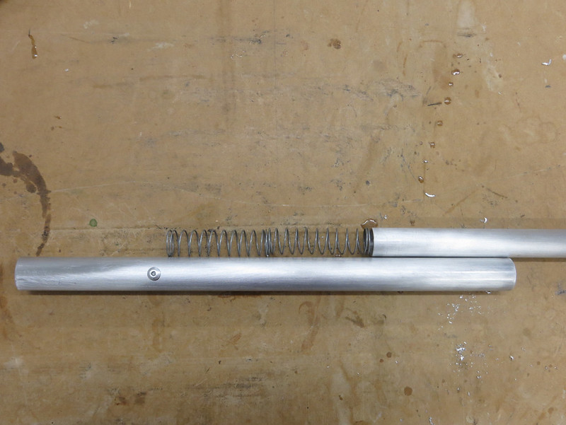 20150706_004 by Alan, on Flickr
 20150706_005 by Alan, on Flickr
 20150706_002 by Alan, on Flickr
 20150706_008 by Alan, on Flickr
I think they look pretty good once painted black:
 20150725_002 by Alan, on Flickr
Alan
I've been using a spring loaded aluminum tube with aluminum angle riveted to the hull. You can find more attractive ways of mounting it to the hull if you're worried about aesthetics. It's easy to make and quick to adjust on the water.
20150706_004 by Alan, on Flickr20150706_005 by Alan, on Flickr20150706_002 by Alan, on Flickr20150706_008 by Alan, on FlickrI think they look pretty good once painted black:
20150725_002 by Alan, on FlickrAlan
G
Guest
Guest
You all never cease to impress. Alan, if you please, how do you fabricate the metal L bar? The cuts look very clean. If I tried it, I'd probably just end up doing a raggedy slap dash job with a dremel cutting wheel or some such.
You all never cease to impress. Alan, if you please, how do you fabricate the metal L bar? The cuts look very clean. If I tried it, I'd probably just end up doing a raggedy slap dash job with a dremel cutting wheel or some such.
They're not clean. They're a complete butcher job and I'm thankful to still have my fingers every time I finish. But a little clean up with the file and spray paint has them looking pretty good.
I've been cutting them in my big 12" metal chop saw. It's far from a perfect method and since I need to make another one in the next week or so it's time to come up with a better (safer) method. The good thing about aluminum is that when the blade binds it just bends the hell out of the stock rather than sucking my hand into the blade.
Alan
Great foot brace design Mr. Gage.
I have successfully cut aluminum with a sliding compound mitre saw, as well as a radial arm saw. Good quality carbide blade, but used, worked great.
Does the width of kerf from your metal chop saw differ much from a standard carbide saw blade?
I have successfully cut aluminum with a sliding compound mitre saw, as well as a radial arm saw. Good quality carbide blade, but used, worked great.
Does the width of kerf from your metal chop saw differ much from a standard carbide saw blade?
Similar threads
- Replies
- 42
- Views
- 18K
- Replies
- 43
- Views
- 11K