• Happy National Garlic Day! 🧄🚫🧛🏼‍♂️

Laminated Wood Seat frame failure postmortem and re-engineering

Joined
Mar 21, 2015
Messages
441
Reaction score
21
Location
SW Wisconsin/Driftless
Hey all, those who have been following my experimental Strip build may have already seen some photos from my test paddle Monday. Overall, a good test. However.... One item did not work out as well as I had hoped.

My lovely, laminated seat frame did not survive the day.

100_4300.JPG


I'm a little nonplussed about this in two different ways. First, the original failure point is circled in red. I was seated with my weight forward, playing with the trim of the canoe. The slide block gave way at an epoxy joint, and the off-center load then twisted the seat frame.

100_4256.JPG 100_4306.JPG

The slide blocks are hard maple, assembled with thickened epoxy (SystemThree General Purpose + Cabosil) As you can see, in this case I actually had a glue joint failure, rather than the wood grain failure that I would have expected. I find this a bit disturbing, as this is the exact same glue that was used for some of my gunwale layup. The bond area was 3/4" X 1 1/2", under shear load, no peel.

Obviously, I can reinforce with pins, &tc, but I'm surprised that this happened in the first place. I can also flip the blocks upside-down, and set the seats above the slides. There is a steel bushing all the way through at the bolt locations, but this has the seats a bit higher than I planned. Do any of you see anything obvious, other than that Maple apparently does not absorb resin well?

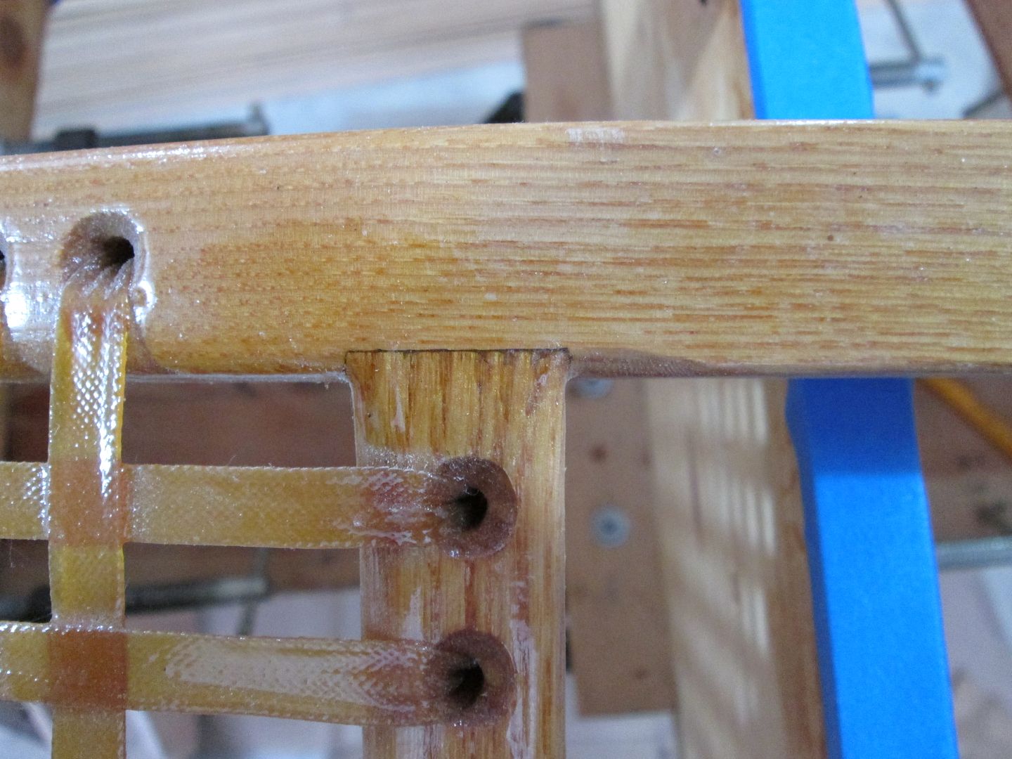
The other disappointment is that the seat frame failed that thoroughly. Take a look:

100_4303.JPG 100_4305.JPG

So, the cedar core cracked, which is not much of a surprise, but I'm also seeing in a couple of locations that the glue bond failed on both ends of the pins. I could just pass this off as the seat taking a load that it was not designed for, but I'm not that large, and I'd hoped for a little more resilience. I'm hesitant to trust the other frames at this point.

I really liked how these felt in hand, so I'm considering rebuilding in hardwood. I have plenty of Cherry and Walnut available, as well as more Maple, or we have Red Oak coming out our ears. (I Really don't want to do Oak for anything canoe related, though.) Even a full hardwood frame does not, though, fix the joint strength issues. Any insight would be welcome, though I'm afraid a replacement will end up heavier (These were about 2# including webbing)
 
They were pretty seats, but the Cedar was not the best choice. A friend made some beautiful Cherry seats one time. They gave out on his first trip to the BWCA.. So your not the only one it's happened to.

I've always used Ash., And yes it's heavy. It flexes if you watch the grain. and can be cut thinner. I have a factory webbed Ash seat that is a lot lighter than the ones I make, and it holds up well !
 
That general purpose epoxy has a tensile strength of 7,000 psi. The technical data sheet does not list the lap shear strength, but their structural adhesive (T-88) lists a lap shear strength on maple as 1,800 psi (with a substrate failure). You would need to do the calculations to see if you had adequate surface areas; it's safest to assume ALL loads are carried by a single joint, as the load distributions may not be as uniform as you might hope. (and clearly they were not )
Beyond that, you could provide some additional space for the epoxy on a subsequent build, even so far as to use shallow counterbores on the mating surfaces, for the epoxy to lock in to. Also, epoxy joints don't like to be clamped and starved...that could have been the source of your initial failure.

Your seat frame laminations should be in the other plane, so you could take advantage of the wood's modulus rather than tax the tensile strength of the epoxy. Likewise with your lacing holes, you compromise the beam strength by drilling the holes through your most important section. The holes should pas through your least valuable (in terms of section modulus) section.
I am surprised that you also sheared the pinned joints. Again, a calculation is in order, assuming ALL loads on a single joint.

Also, your method of hanging the seats did not limit the joint stresses to shear only, there was still a moment there. You would need a double shear mount, but that is likely not practical, given your application.

You probably saw the tests that I did on seat cleat strength. If you used hull mounted cleats, you could still use rails to provide seat adjustment. Simply supported seats are a more reliable means of load distribution.

Speaking strictly for myself, I prefer a bottom mounted seat support. It allows simple components, and as a side benefit, allows paddlers to move their legs freely around the boat. This is especially helpful when weight transfers are a must.

Lastly, I wouldn't fret too much over failed seat frame...we've all had it happen to us before! It's all part of the design refinement. How would you know where the limit is, if you didn't exceed it?!
 
That was my thought was the joint was glue starved. On hard woods like maple I've been known to to use a toothed plane to scratch the joint surfaces so all the epoxy can't be squeezed out.
As for the seat joint failure, how about finger joining the corners so they interlock?
Jim
 
Looking closer, I agree with Stripperguy. Your joining technic, and hanging method allow too much movement side to side.
As well as wood orientation. Pins through hard wood would be much better.
 
Last edited:
Thanks for the feedback so far. I'm seeing that I need to re-evaluate some of my mental models here.

First, Boatman53 That's a good thought about starvation. Those joints weren't clamped, though. I just gently pressed until everything seemed moderately bedded down, and left it alone. The part that came off, as far as I can tell without a good magnifier, has a layer of glue about 2x the thickness of standard 20# printer paper. I didn't use finger joints because I knew that the cedar layers (Yeah, I know, wasn't a good idea) would not take well to them. Otherwise, they sound like a good idea.

I'm starting to wonder if I overdid the cabosil in this epoxy - fresh, not kicking off yet, it was somewhere between Mayo and Peanut Butter. The slide block joint that failed was exactly 1 in[SUP]2[/SUP] in area.

If I was considering a redeux, any idea how much of a difference a physical tooth would make? I don't have a toothed plane, but I could take a medium-coarse saw blade, and scratch sideways....

When I made the decision on how to orient the frame members, I proceeded on the (Naive) assumption that the major loads on the frame would be vertical. I thought of an I-Beam, or truss, where the top and bottom faces carry a tensile/compressive load, and the web or cross bracing just maintains their separation, as long as the loads are not enough to crush it. (I know that this model of an I-beam is a simplification, but for seat of the pants design, it usually serves)

I know better. I should have thought about what the force components look like when a force is applied perpendicular to a taut line. If I followed the math in my (Basic) physics book correctly, I've calculated that:

- If we only had webbing running one way
- If my total weight was on the webbing (135#)
- If the webbing deflected so that it made a 10[SUP]o[/SUP] angle with horizontal (seems about right, but not measured)

The total side force on the seat frame members would be around 765#. I have not tried to figure the torque this load would place on the joints, because I don't know where to fix the center of rotation, but it would not be insignificant.

These numbers are higher than reality, as I would never have my whole weight on the webbing, and the load would be spread across two sets of frame members. It does show which way I need more strength and stiffness... and I might have larger friends in the canoe at some point.

stripperguy Given the above (and any refinements or corrections of understanding that you choose to add) would I be understanding you correctly that the preferred profile for a frame would be the classic flat frame members, major dimension of the cross section being horizontal, with any through frame fittings/holes being drilled through the minor dimension, vertically?

I'd expect that due to their geometry, such joints would be stronger against racking forces, as well.

One thing that I'm stewing on a bit is that I really liked the bent edge on the front seat. Do you think I could get away with laminations if I Increased the section width?


A major consideration that lead me to avoid hull cleats and/or bottom fittings is that they all seem very permanent. I've not seen a way to secure them that would not mean having to break an epoxy bond if I decide I have to move or change one. When I hang from the gunwale, I have the option of removing a few bolts, and the hardware can disappear on a few minutes notice, leaving a bare hull. This would allow me to have a seat mounted on one end, but still be able to run Canadian Style against the hull from the other end if I want to change it up while solo.

If you have any thoughts or references, or ways of dealing with my concerns (Perhaps I'm making it all up?) I would be willing to consider alternatives, but I'm sort of going for an easy-to-reconfigure arrangement. (Don't have room for a fleet, like Jim Dodd, So I can't have a different boat for every occasion! ;)
 
I don't know if I really makes a difference but when I'm gluing up pieces with thickened epoxy I first lightly coat them with non-thickened epoxy and let that sit for a few minutes before slathering on the thick stuff and bonding them. I always wonder if the thickened epoxy by itself makes as good of a bond with the wood.

Alan
 
Thanks for the feedback so far. I'm seeing that I need to re-evaluate some of my mental models here.


stripperguy Given the above (and any refinements or corrections of understanding that you choose to add) would I be understanding you correctly that the preferred profile for a frame would be the classic flat frame members, major dimension of the cross section being horizontal, with any through frame fittings/holes being drilled through the minor dimension, vertically?

No...increasing the width of the beam will only get you a linear increase in strength. Increasing the height will gain you a benefit cubed. (BTW, increasing the length will cost you an inverse squared reduction).
So, it's best to increase the section where you get the biggest benefit. However, by drilling holes through the vertical plane, you effectively reduced your strength by, uhmmm... too much!

You can still laminate your droop rail seats, just laminate them in the other plane. Yeah, I know, you'll need larger pieces of wood stock to start with, but you'll end up with a strong, attractive, and comfortable seat frame that will be unique.
I still think your hangers were starved, but with some additional notching, slotting, counterboring, and careful assembly, you shouldn't fail that joint again.

As for the Cabosil effect, I tested such a joint a while back and reposted the results here:

http://www.canoetripping.net/forums/...-seat-mounting


Hope this helps guide you.
 
Thats a lot of little pieces glued together. May I ask why you wouldn't have considered making those out of a solid piece of wood?

I'm a big fan of using traditional joinery where you can (cabinetmaker here). I'm sure that the specification on the epoxy shows it will be fine, but to my way of thinking you will lessen the risk of failure if you use fewer parts. Also for the seat frame, if that was a lap joint vs. a dowelled joint it may have not failed.

Just my nickels worth, and not meant as a criticism at all but as a discussion point. I think you've made a very beautiful boat that will last for years to come.
 
blackfly Primarily, I wanted something lighter than any of the hardwoods I have access too. Also, done properly, a composite can actually be much stronger than the average wood that I can get. Please note, none of the lamination joints failed - I had those corners fail, and the front of the seat split down the middle.

A lap joint, or even a box joint/finger joint may have been better. I was not sure I would be able to pull it off with the cedar core, though.

The split was in the cedar that I had used for the core there. I don't think that the structure split due to a flex failure, rather I believe that the pins in the joint twisted and pried it apart from the inside.

stripperguy I think that we have miscomunicated at some point. This is probably due to the fact that I have a very hard time putting my (Very visual) mental models of mechanical things into words.

Just so we can visualize together:
seatframes.PNG

Just a bit of a 3d model of the frame that I had, and a more conventional alternative. Gold to indicate lacing hole locations.

I had originally assumed that the major load on this frame would be in line with the red arrows, and indeed, the beam sections have turned out very stiff and strong for loads in that direction. (can hold my full body weight at 12" cantilever, no appreciable flex)

I'm now wondering, though, if having most of the passenger weight on the lacing will put the larger load in the direction of the blue arrows. In this direction, the beams are not as strong, and as I understand it, are further weakened by the lacing holes. This would also cause a torque force on the parts, not sure how large, as per the green arrows.

This lead me to the conclusion that a frame more like the one mocked up above, upper right, would be a better bet. But If I understand your last post correctly, you are telling me that is wrong. Have I understood you? Or am I still missing something? If a guy was to insist on laminating, (Not going to commit yet, but just checking) which plane would you run the laminations in?

Sorry, if you can't tell, I've been a bit confused by the verbal/word descriptions so far.
 
I know my seats differ greatly,
IMG_0109_zpsmoqbjk92.jpg

but I notch my rails and fit. This really adds strength when twisting.
Of course the joint is filled with thickened epoxy, and held together with one 3/16" hard wood dowel
I hope this pic helps.
 
sailsman,
Nice models...Are they just for visualization? Or have you assigned the proper engineering properties and defined the constraints and loads? If so, you should have all your answers in hand.

The holes in your failed frame give additional leverage to the lacing, effectively increasing any moments created by loading the lacing. The holes in the upper right concept will reduce these moments, as well as maintain the strength in the vertical plane.
If your beam section was adequate for the cantilevered loads (at a 12" distance between supports), then why a failure?

A lap joint similar to what Jim has shown is pretty standard, and with good reason. However, be sure (if you choose this design) to keep the dado on the top side of the rail, so that any deflections will make the joint tighter.

While laminating in the other plane from what you initially did should take advantage of the shear modulus of the epoxy and the wood, it appears that you can go either way without undo consequence. Your failure seems to have been caused by undersized pins at the joints and starved joints at the hangers.
If I have time later this evening, I'll whip up a model of your seat frame and apply loads and constraints to see the resulting stresses and deformations.

Lastly, here is a photo from a previous build showing one a seat frame and one of the support cleats. Note the lap joint orientation, as well as the height to width ratios on the seat frame. And remember, deflections that do not result in yielding are elastic and of little consequence, unless cyclic fatigue becomes an unlikely issue.

DSC_9940.JPG
 
I don't know if I really makes a difference but when I'm gluing up pieces with thickened epoxy I first lightly coat them with non-thickened epoxy and let that sit for a few minutes before slathering on the thick stuff and bonding them. I always wonder if the thickened epoxy by itself makes as good of a bond with the wood.

Alan


One thing that I noticed when I skim coated my gunwales was that the Cherry and Walnut drank the thin resin, the way they would absorb varnish or a sanding sealer. The Maple did not. Makes me think that maple just intrinsically has less bond strength than other woods in this application, making an added physical tooth more of a necessity, such as a pin, or scraping up the surface with a toothed plane, etc.

Jim Dodd Thanks for the close-up. Worth considering, though I wonder what would happen if the one rail did not continue on through?

stripperguy The 3d models are just pretty. They're made in a program that is intended for art and animation, with no engineering support at all.

Looks like you are into some serious seat frames. One thing I noticed about the half-lap's orientation is that it is built with the load location in mind. If that frame were supported differently, the joint's geometry might need to be altered.

I'd agree that the joints themselves were the main problem here, but improving them is going to mean some changes in the beam composition to support better joints.

The increased solidity from the cleat mounting system is somewhat tempting. I'd have issues, though, with a lack of flexibility. My Canoe will probably be used about 75% solo, but even then, I'm not set on any one favorite configuration. Has anyone ever used a slide system that was intended to be entirely removed from time to time?

I'm well aware that many resilient systems have some elastic deformation under load, any attempt to reduce that would be for the psychological security of passengers....

When I say that the beam can hold my body weight, what I mean is: If I had a sturdy enough clamping system at the red arrow, I could suspend my weight at the yellow one.
100_4311.JPG

The beam that broke, on closer examination:

100_4309.JPG 100_4310.JPG

Notice that the lower pin survived? When my slide block failed, this corner got a major, unexpected load. It was pressed down, (red arrow). The lower pin held in place for a moment, and the side frame was being held up at the other end. This caused a torque along the green arrow's direction, and the upper corner pressing into the top of the front beam, while the pin pulled at the bottom, resulted in shear forces along the yellow arrows.(simplified) This stressed the beam in it's weakest direction, One that I had not expected to take any measurable load. Even a single, vertical hardwood pin through the layers would have stopped that crack, though I believe that the joint still would have failed.
 
FWIW, when I do my laminated seats I alternate the strips, Ash, Cherry, A, C, A, C, A. I see you have a cedar sandwich with all the softwood in the core. Even when I've had an oops and the stack milled out smaller than originally intended the seat has been strong enough. Mind you, I don't use dowels for joints, I hand make a mortise and tenon joint which is epoxied together. My lamination is glued up with wood glue. I have not yet done a laminated framed to be laced, when doing caned seats it is usually a reproduction type situation so the rails are flat and solid wood.

Karin
 
Just for kicks, Old Town probably made over a million seats for their wood and canvas canoes. Every one of them dowelled. I suspect they did not even use glue - I have never seen any residue. Maybe relying on the fit of the dowels, the cane and varnish to keep things tight. Often times the holes for the caning go through the dowels! The seats held up very well. I have rarely seen a broken one. My shop teacher had an expression - "KISS". Keep It Simple Stupid.;)
 
Spent some time out last weekend with temporary seats, experimenting and showing the canoe off to my friends.

100_4312.JPG 100_4313.JPG

Yeah, I know, not pretty. They did function, and I found out something important: These are way too high, especially if most of the load is people. The tops of the temporary planks came out at 4" below gunwale height. Combined with the curved bottom, this created quite the rolling moment....I had a friend, ~160#, canoes a bit. (Takes the cabin canoe out to fish, and does the boat handling when companions don't have a clue) This person was not able to hit and switch without rolling a gunwale under. I'll admit that we were heavily loaded, Three people totaling ~460#, and all of that weight was at seat height, but still....

This brings me closer to following @stripperguy's advice and going with hull brackets. I'm starting to seriously consider the option, though I really like the clean hull interior...

I also found that I may want to take the seats a little further into the stems than I had intended. This brings another question: What is a reasonable width for canoe seats? the last batch came out at 18"wide, and I doubt I can take them any further into the stems because of the hull form.

Mihun09 I would have alternated my hard and soft wood if I had anticipated (Say rather, analyzed) the load situation better. I did not consider a load like that at all. My primary concerns were: vertical load beam yield, and light weight. Next set will be better thought out.
 
First I have to say the canoe is beautiful. Nice job!! Looking at the above pictures I'd be concerned that the way the mounts are setup you're putting a large torque on the hull. The center seat looks like the mount is cantilevered about six inched inside the hull. If the seat to mount joint flexes at all then the torsion has to absorbed by the hull. My lightweight hulls (especially without thwarts) wouldn't like that at all, maybe your build is much stronger than mine in which case I guess it's OK.

Good luck. David.
 
I'm not comfortable with the way you are hanging the seats. As Dave says there's a lot of torque on the hull. ​ Those supports have to add a lot of extra weight, and take up a lot of space, that you might need for gear.

The canoe looks great, except for those braces.
Sorry It's just my opinion !

I'd be real tempted remove those braces, and glue blocks to the inside, and mount my seats to them.

Jim
 
Back
Top