Welcome to an unconventional build thread. I enjoy reading these sorts of things and have learned so much from others that I am happy to post my own projects. I welcome community input and hope we can learn a few things along the way. This is a construction forum, so no need to tell me I'm crazy (I'm fairly aware of that) or that I should just buy a faster secondhand boat. I'm sure you all appreciate the personal satisfaction that comes out of a home build, and that's what I'm in this for too. I'm an amateur and this is a hobby: There's a good chance the boat will be a failure, or will not live up to my expectations- and that's okay by me. I say 'unconventional' in that I really haven't seen this type of canoe build executed and published before. A lot of my research has come from composites forums and power/sail boat construction forums.
Design Goals:
-Purpose is solo multiday adventure racing (340, Safari, Border Route, etc). Unbounded creativity, it seems, can only live in the unlimited class events.
-Secondary purpose is fitness paddling: going hard and fast for 1-3 hrs- for fun.
-Lightweight enough to significantly effect portage weight (grand portage is 9 miles). Current calculations are targeting a 20-25lb boat.
-Design Displacement for Paddler+Boat+3 days equipment= 225lbs.
-Large favored secondary stability for a tired paddler.
-Able to be efficient with single and double blade.
-Able to be re-entered in deep water.
-Ruddered to manage beam winds for long distances.
-Design favors deep open water vs shallow narrow water.
-All-day speed will only be limited by 1) all day stability [it is much faster paddling on the water rather than in the water] and 2) my level of fitness.
Build Goals:
-Take a hull from design all the way to finished boat.
-Use vacuum resin infusion for final boat assembly.
Inspiration:
- First, I have to thank Alan Gage, who has helped with many questions and knows far more about design dynamics (and paddling in general) than I do. He sent me a lines plan of his X-canoe, of which this design is really just a big set of modifications. You are encouraged to reference his well-documented build here: http://www.canoetripping.net/forums/forum/general-paddling-discussions/diy/19929-x-canoe-build
- My current workout/solo tripping boat is a Magic. I have paddled it in waves big enough to hide the horizon (terrifying, but a testament to stability) and I feel like my cruising speed is limited by the design.
-I almost sent away $4k for a Blackwater solo: but thought I could try my hand at a more extreme design while realizing the cost savings and satisfaction of a home build instead. Considering that as an alternative, even with plug and mold construction I am still far under budget.
-I have never seen a Texas/Spencer canoe in person (and online searching shows only few photos and no real specifications), but I think this design is somewhere close to a Landick II.
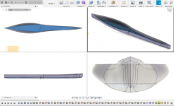
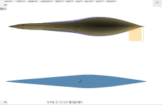
Specs:
-19'6" length overall
-waterline beam at design displacement: 22"
-displacement at 3.5" waterline: 226lbs
-finished weight: 20-25lbs.
-Rocker: 1.5" bow, 0.75" stern.
-most other standard measurements don't describe the boat well, due to the unconventional design.
Design Goals:
-Purpose is solo multiday adventure racing (340, Safari, Border Route, etc). Unbounded creativity, it seems, can only live in the unlimited class events.
-Secondary purpose is fitness paddling: going hard and fast for 1-3 hrs- for fun.
-Lightweight enough to significantly effect portage weight (grand portage is 9 miles). Current calculations are targeting a 20-25lb boat.
-Design Displacement for Paddler+Boat+3 days equipment= 225lbs.
-Large favored secondary stability for a tired paddler.
-Able to be efficient with single and double blade.
-Able to be re-entered in deep water.
-Ruddered to manage beam winds for long distances.
-Design favors deep open water vs shallow narrow water.
-All-day speed will only be limited by 1) all day stability [it is much faster paddling on the water rather than in the water] and 2) my level of fitness.
Build Goals:
-Take a hull from design all the way to finished boat.
-Use vacuum resin infusion for final boat assembly.
-Target 60% fiber volume ratio for lightest/strongest boat.
-Unlimited fiber set-up time for busy solo builder dedicating "a few hrs here-and-there."
-Necessitates male plug and female mold- relatively high waste for non-production canoe.
-(Much driving the choice of build technique is a personal desire to learn the vacuum infusion process and see if I can do it at full scale- there is a bit of a gamble as to whether or not it will work or if I will ruin $800 worth of materials in a single 40 minute infusion.)
-Timeline: unknown. This might take awhile, but I hope to have it in the water this summer. -Unlimited fiber set-up time for busy solo builder dedicating "a few hrs here-and-there."
-Necessitates male plug and female mold- relatively high waste for non-production canoe.
-(Much driving the choice of build technique is a personal desire to learn the vacuum infusion process and see if I can do it at full scale- there is a bit of a gamble as to whether or not it will work or if I will ruin $800 worth of materials in a single 40 minute infusion.)
Inspiration:
- First, I have to thank Alan Gage, who has helped with many questions and knows far more about design dynamics (and paddling in general) than I do. He sent me a lines plan of his X-canoe, of which this design is really just a big set of modifications. You are encouraged to reference his well-documented build here: http://www.canoetripping.net/forums/forum/general-paddling-discussions/diy/19929-x-canoe-build
- My current workout/solo tripping boat is a Magic. I have paddled it in waves big enough to hide the horizon (terrifying, but a testament to stability) and I feel like my cruising speed is limited by the design.
-I almost sent away $4k for a Blackwater solo: but thought I could try my hand at a more extreme design while realizing the cost savings and satisfaction of a home build instead. Considering that as an alternative, even with plug and mold construction I am still far under budget.
-I have never seen a Texas/Spencer canoe in person (and online searching shows only few photos and no real specifications), but I think this design is somewhere close to a Landick II.
Specs:
-19'6" length overall
-waterline beam at design displacement: 22"
-displacement at 3.5" waterline: 226lbs
-finished weight: 20-25lbs.
-Rocker: 1.5" bow, 0.75" stern.
-most other standard measurements don't describe the boat well, due to the unconventional design.